Fusion 360 Press Fit Design Tutorial
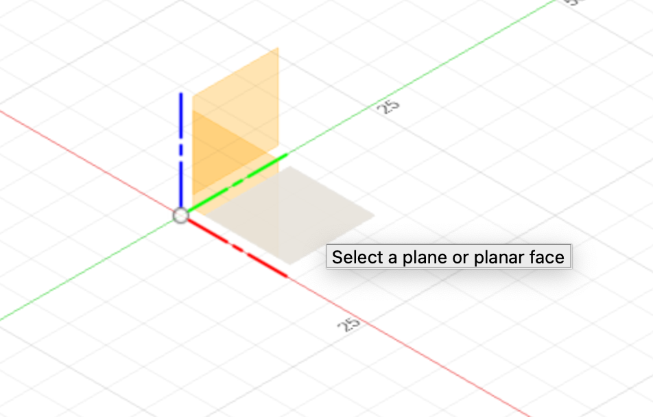
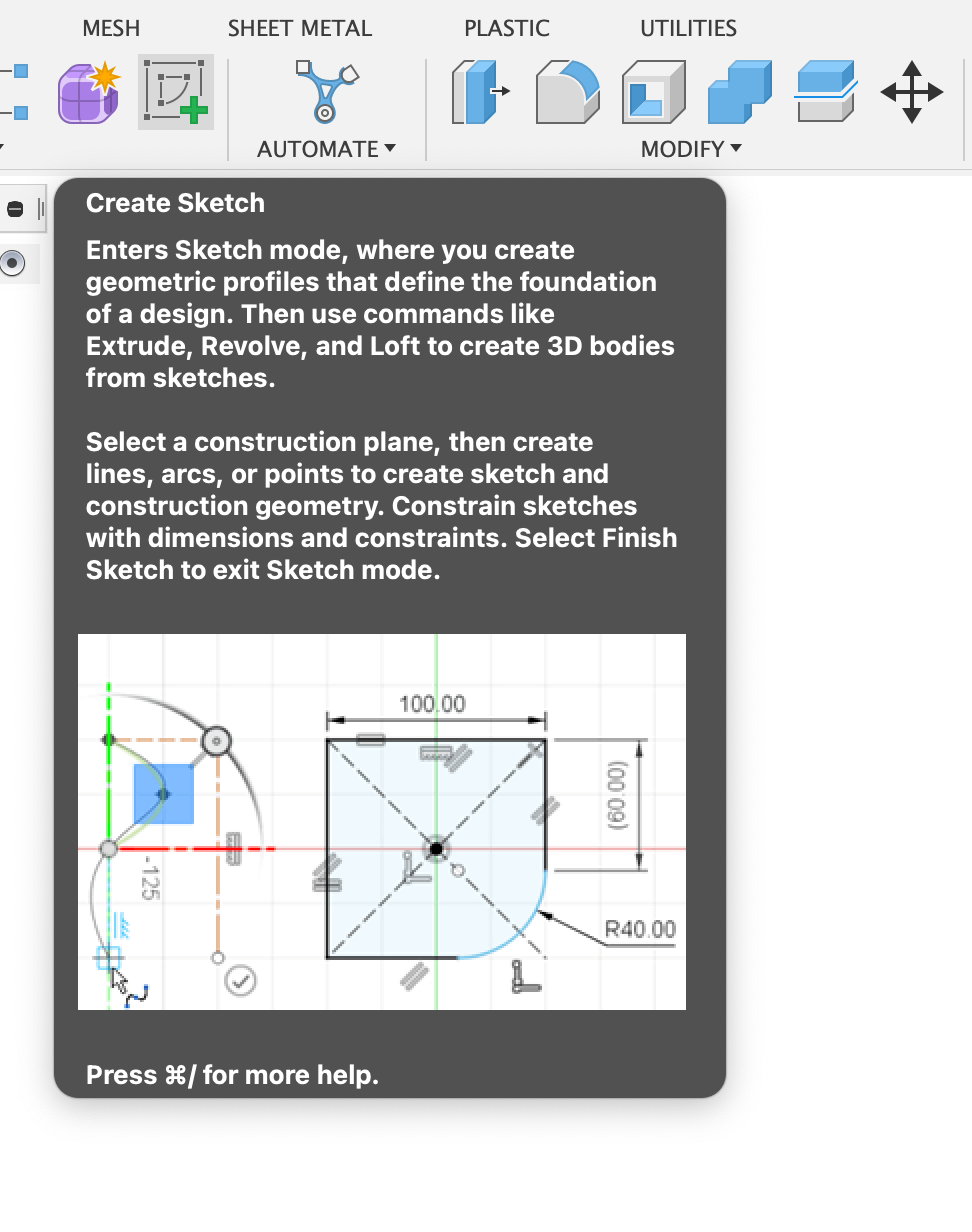
Start by defining a sketch. Click the sketch button on the top horizontal toolbar. The software will then prompt you to specify a plane for the sketch. Select the x-y plane (green and red). Fusion 360's default modeling orientation has the Y axis pointing up, instead of Z-up, which this tutorial uses. To change that, go to preferences (upper-right corner, account icon button).
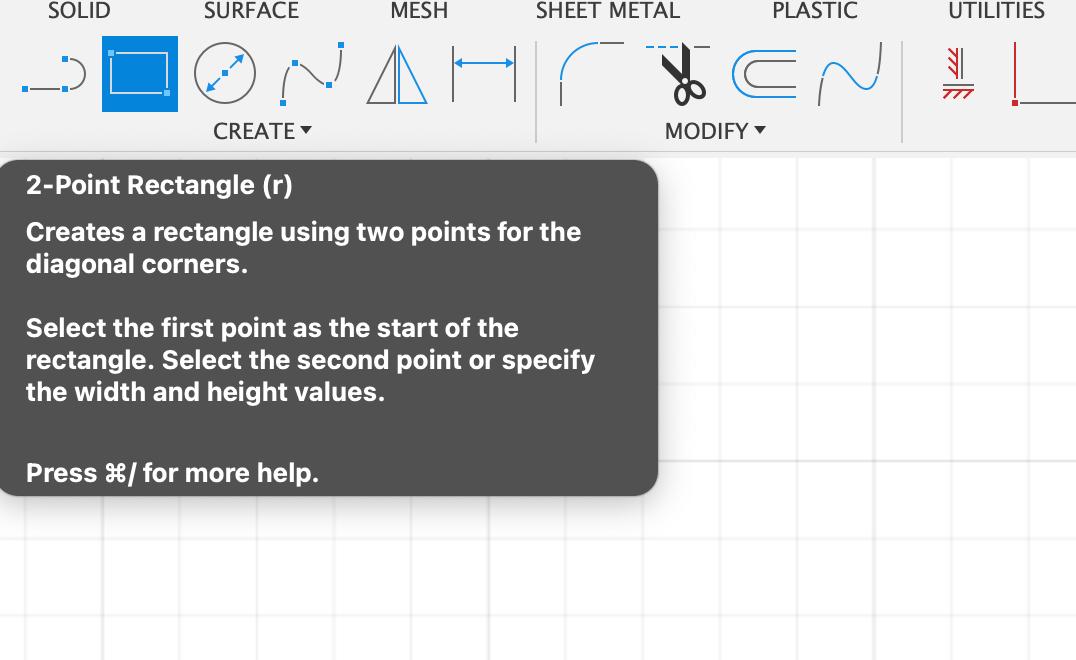
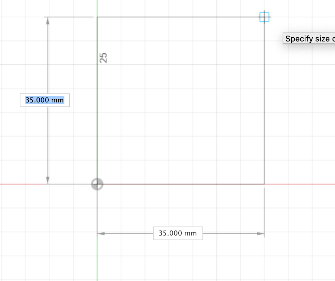
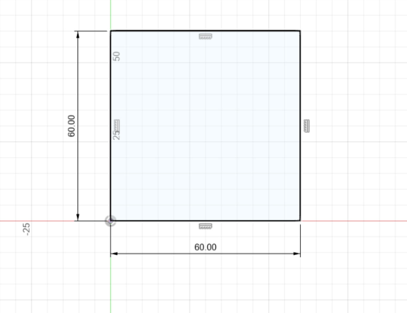
Create a rectangle on the sketch plane using the 2-point rectangle tool in the panel. As you draw the rectangle, you will notice that you can specify its width and height numerically by typing values in the dimension dialog boxes that pop up. These values will constrain the width and the height of the rectangle.
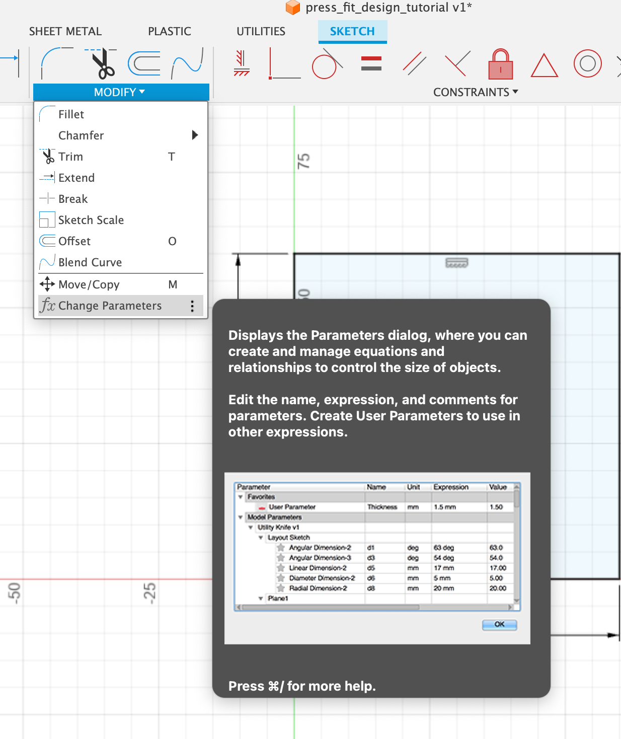
You can specify parameters in a more structured way by using the parameters dialog. You can access this by expanding the modify tool palette and selecting “Change Parameters” at the bottom of the menu.
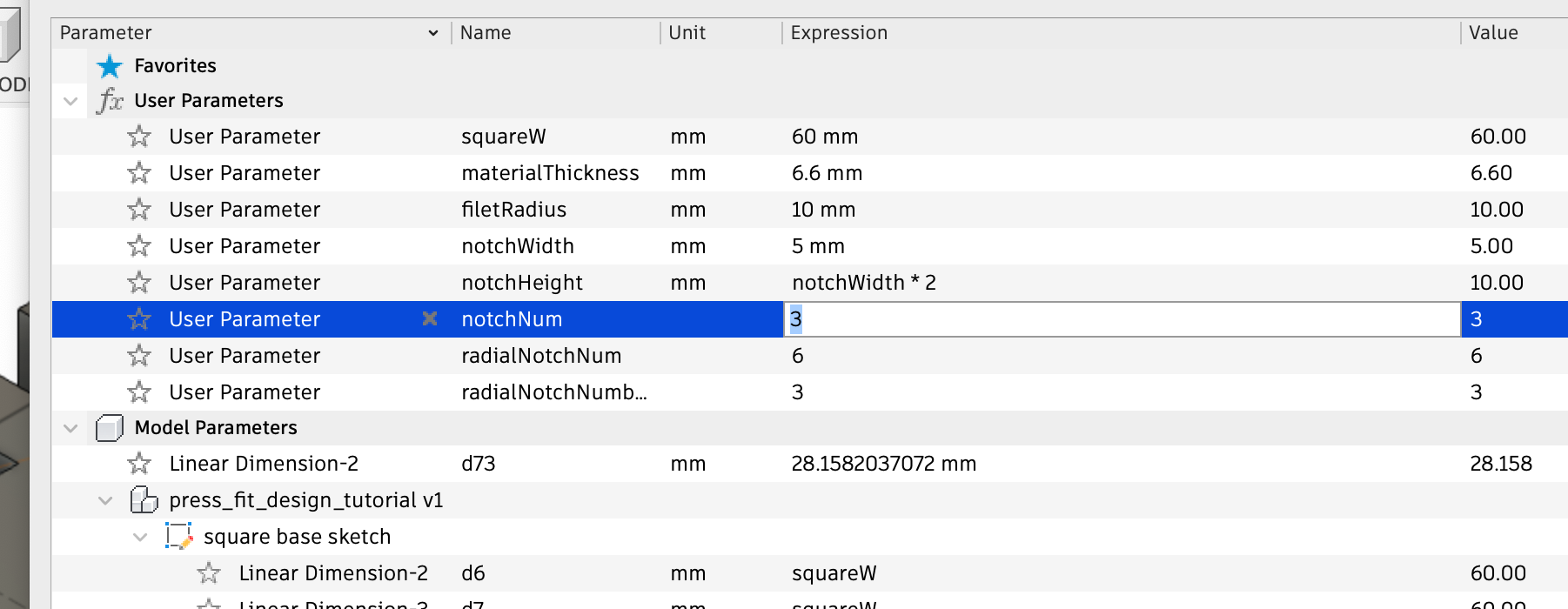
I can create named user parameters in the parameters dialog by selecting the “New user parameter” button. This enables me to define the parameter name and its value. The value can either be a number, OR a mathematical expression (e.g. notchWidth*2). Here, I’ve defined a range of values for specifying the dimensions of a press-fit square piece.

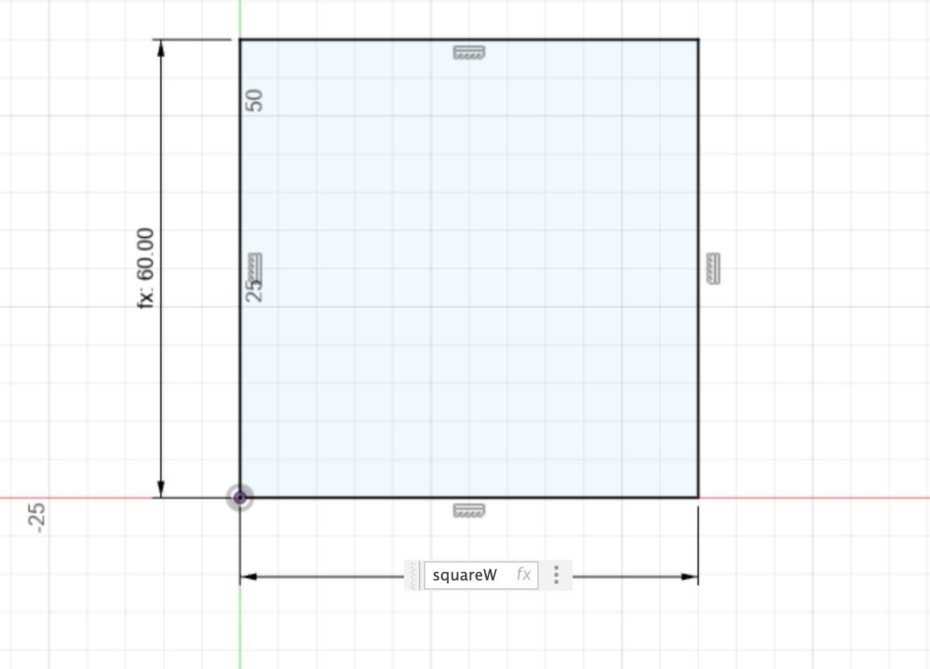
Returning to my sketch, I can dimension my rectangle based on my user parameters by clicking the dimension and entering “squareW” for both the width and the height.
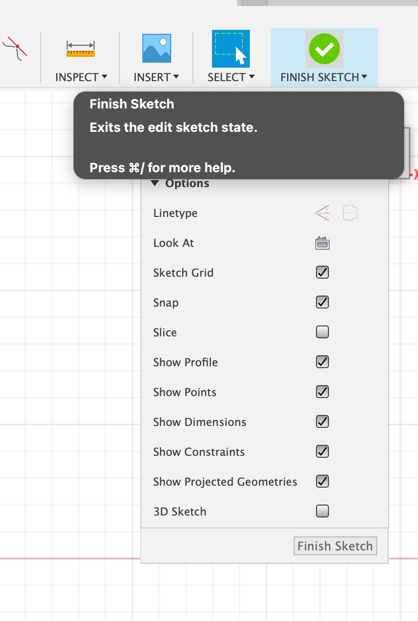
I can then exit the sketch mode by hitting the green finish sketch button.
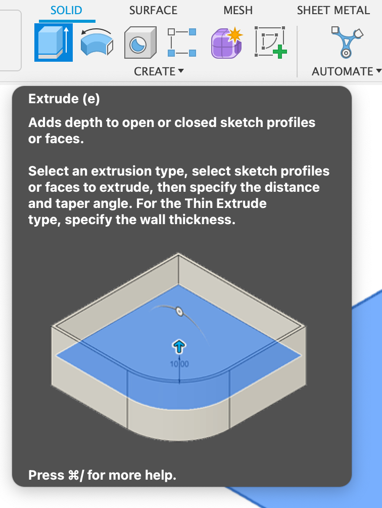
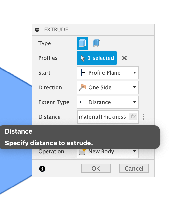
I can convert a 2D sketch into a 3D solid by using the extrude operation. Selecting extrude brings up a dialog in which I can select the sketch plane I wish to extrude and specify the distance. I’ll set the distance-to-user parameter to the material thickness I defined. This corresponds with the thickness of my material for laser cutting.
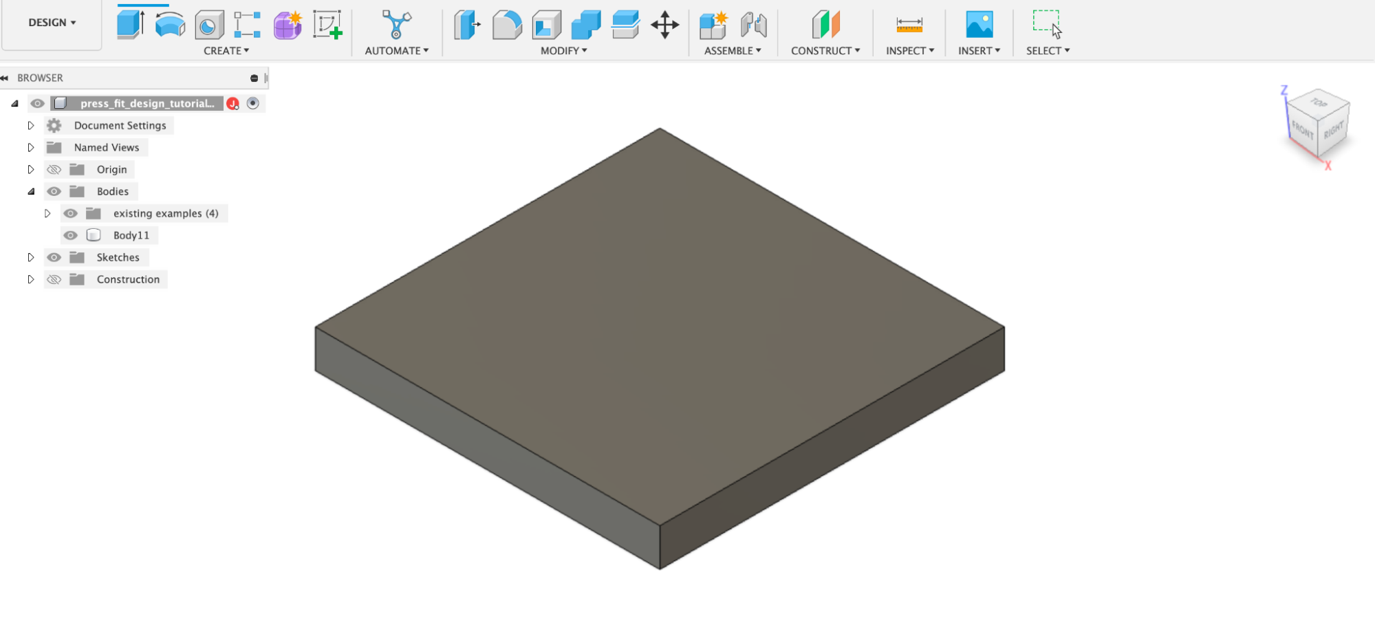
To create the notches, I’ll create a new sketch. However, rather than create it on one of the planes at the origin, I will create the sketch on a planar face that corresponds to one of the faces of my extruded square. This lets me create a sketch relative to the dimensions of that face.
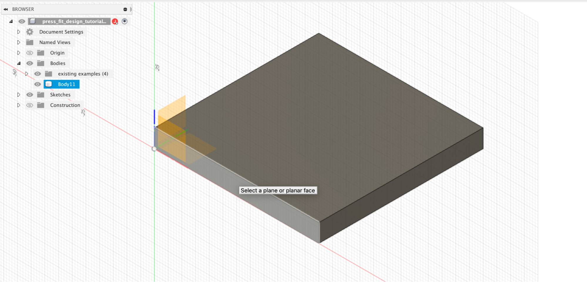
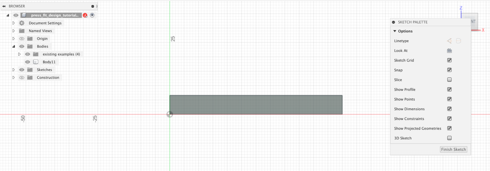
I’ll create a second rectangle with its lower-left corner aligned with the base axis of my extruded rectangle. And dimension it with the height set to material thickness and the width set to notchwidth
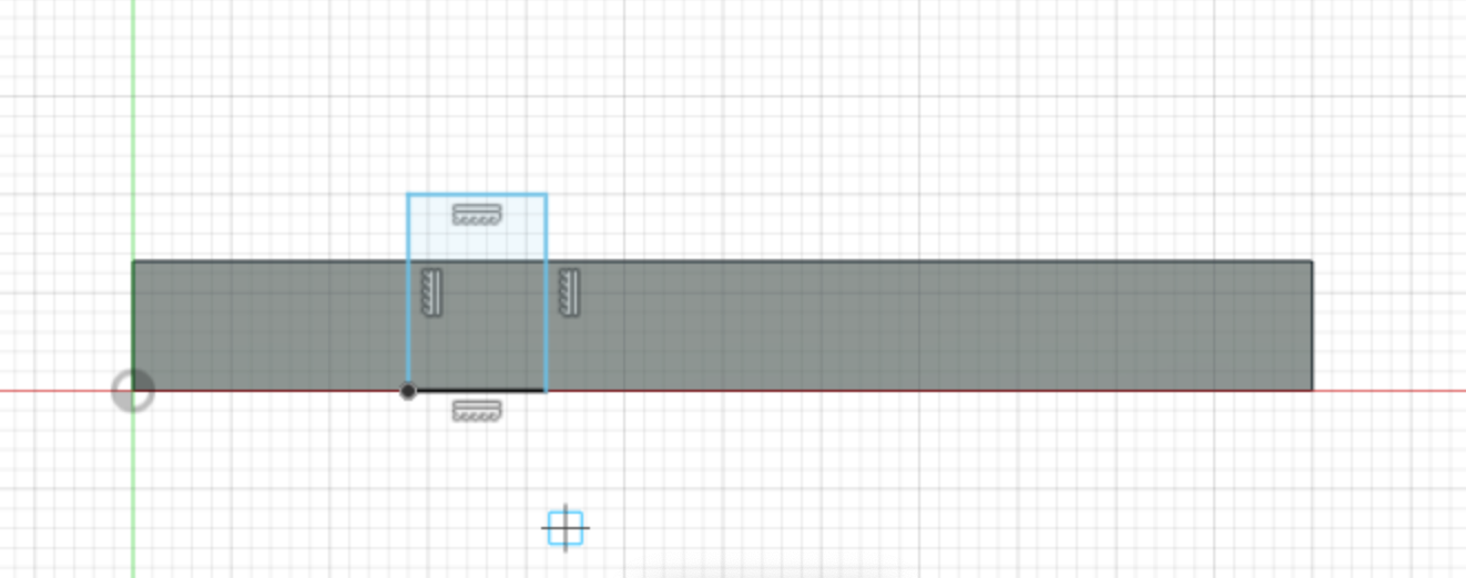
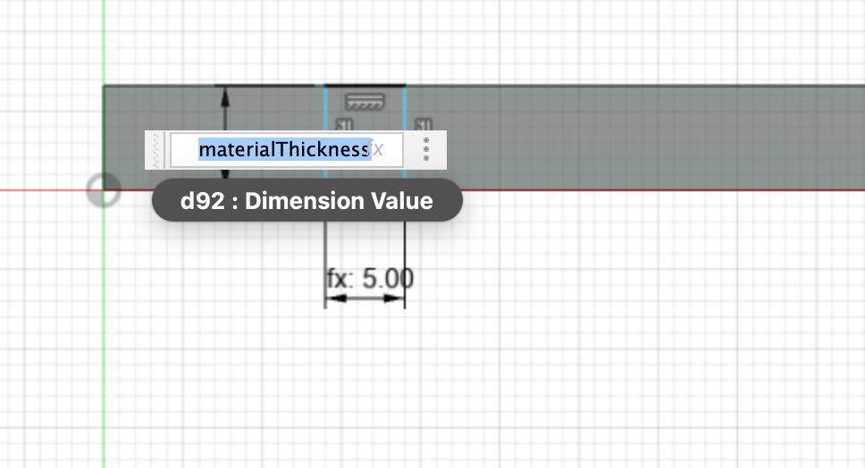
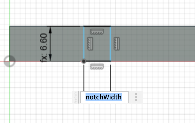
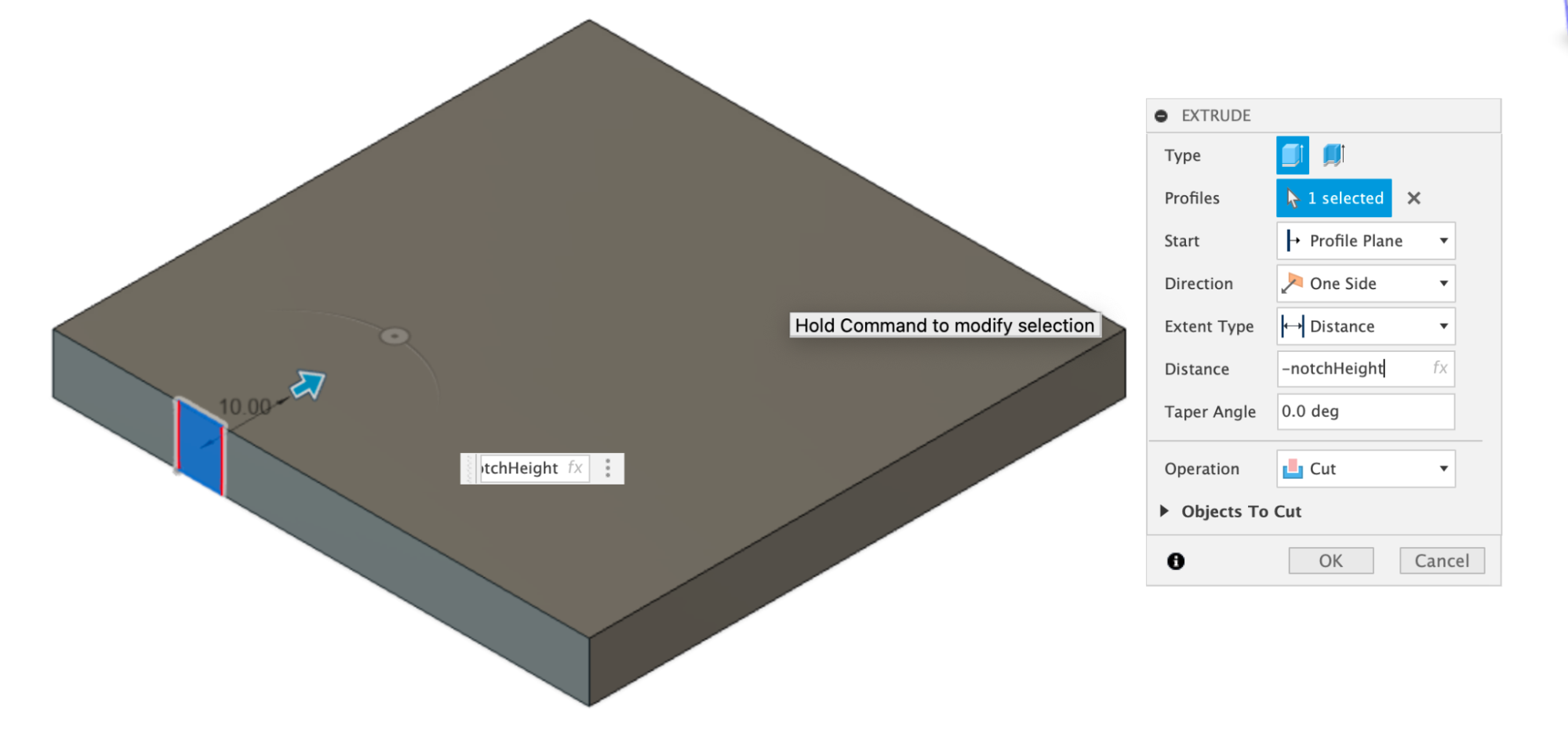
Then I’ll exit the sketch and use the sketch geometry to convert this feature into a cut in my 3D solid. I’ll select the extrude option and select the sketch profile. I’ll set the distance to -notchHeight, which will create a cut operation in my solid.
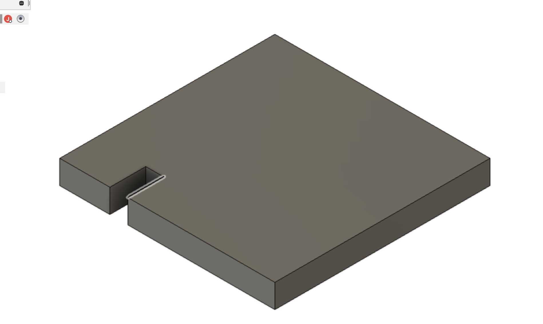
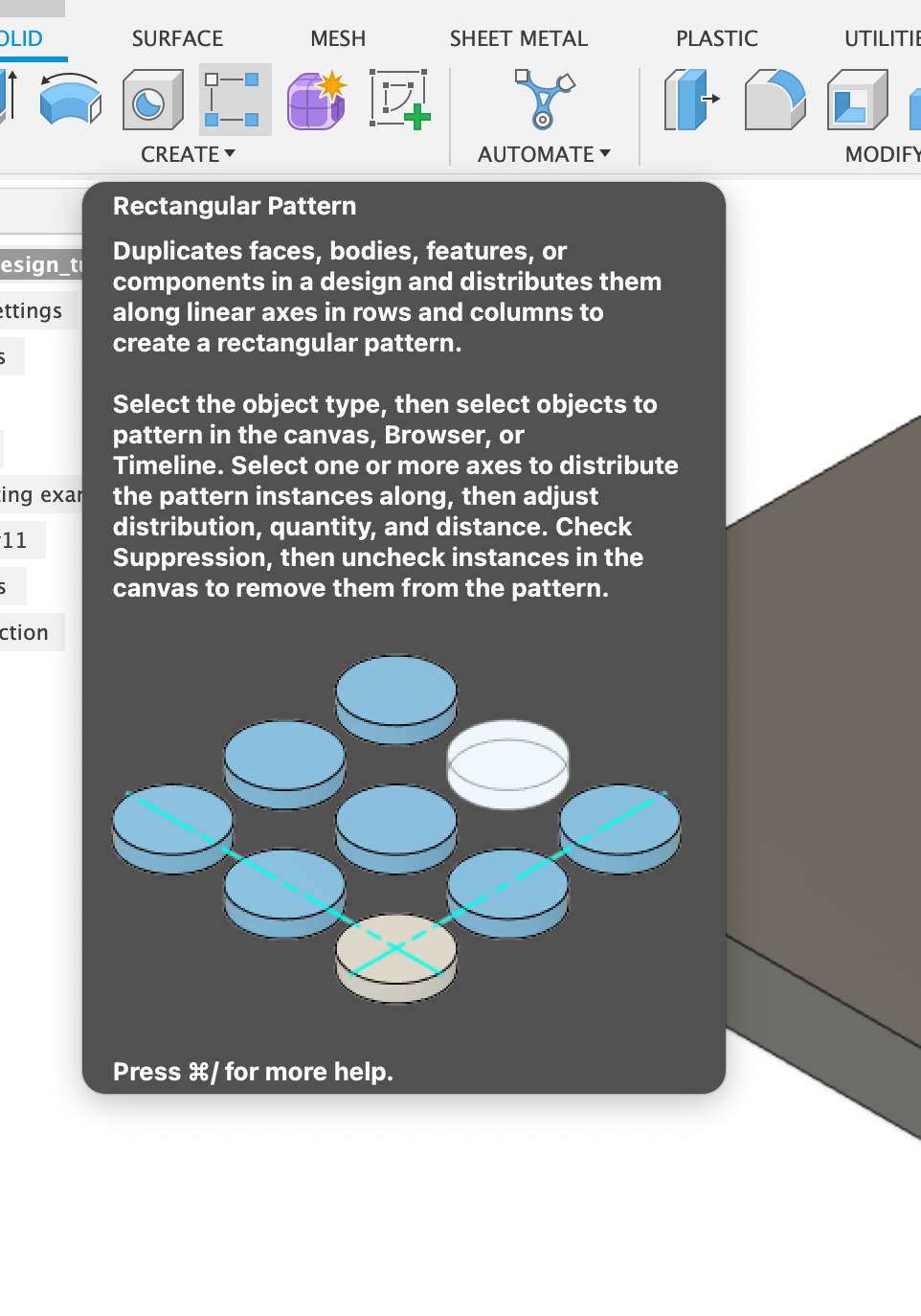
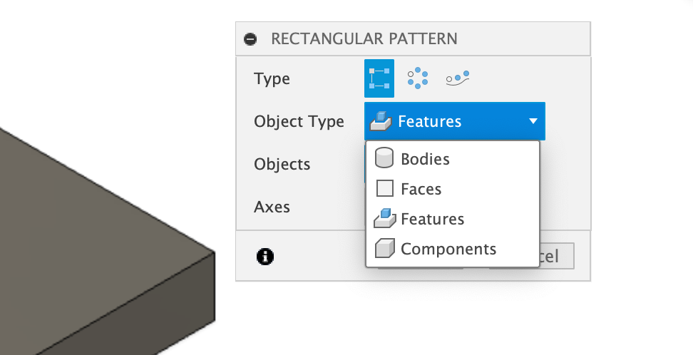
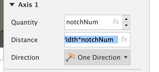
I’ll duplicate the notch along the edge by using the rectangular pattern tool. This will create a design in which my press-fit piece has multiple points of contact along a single edge. This is optional! I’ll set the object type to Features, which allows me to select the notch, and then set the quantity to my notchNum parameter. I’ll set the distance to notchWidth × notchNum. This will create even spacing.
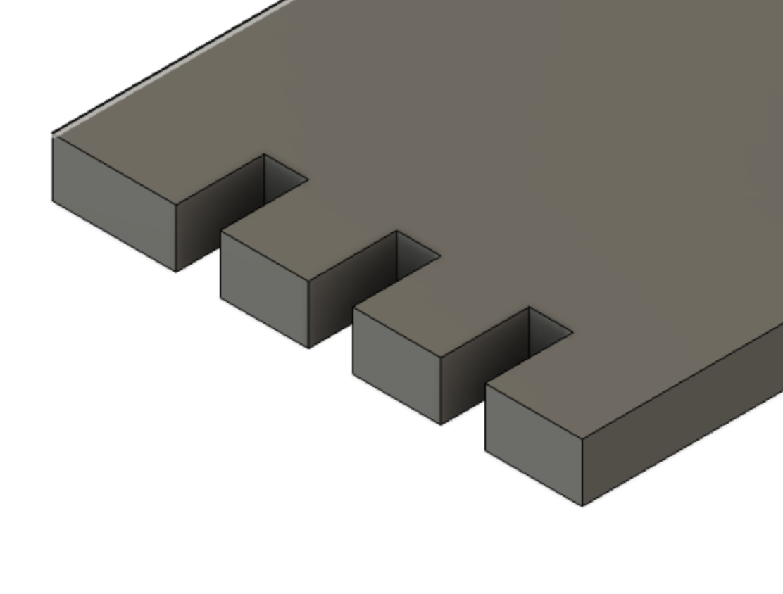
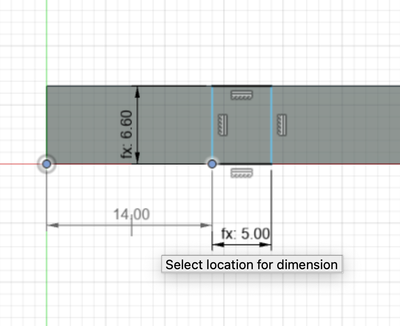
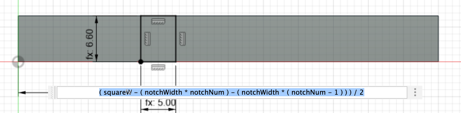
You may find the notches are not evenly centered. I can address this by returning to the sketch along the side of the extruded rectangle. I then create a new dimension from the lower left-hand corner of the side of the rectangle and the lower left-hand corner of my sketch rectangle. I set this dimension to an expression that calculates the distance as a function of the square width, the notch width, and the notch number. This will center the notches.
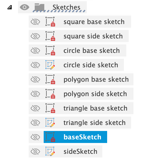
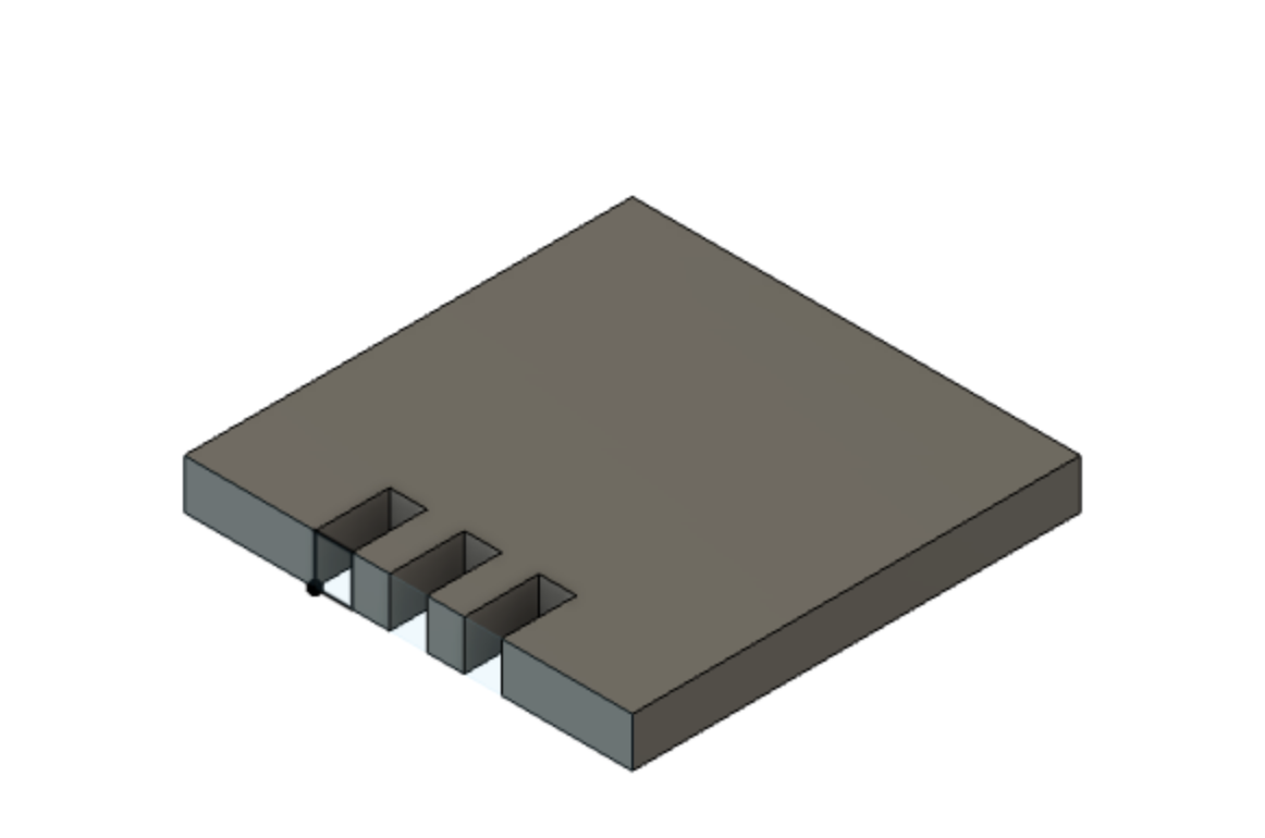
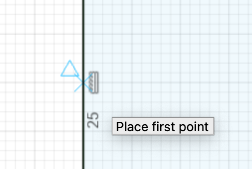
Now I’ll use a similar approach to create notches around all 4 edges. To do this, I need a point of rotation, so I’ll modify the original base sketch to fit my extruded rectangle. I’ll create a center point in the rectangle by drawing two lines across the width and the height that intersect the rectangle sides at their midpoint. You know the start point is at the midpoint when the triangle icon appears as you mouse over the line.
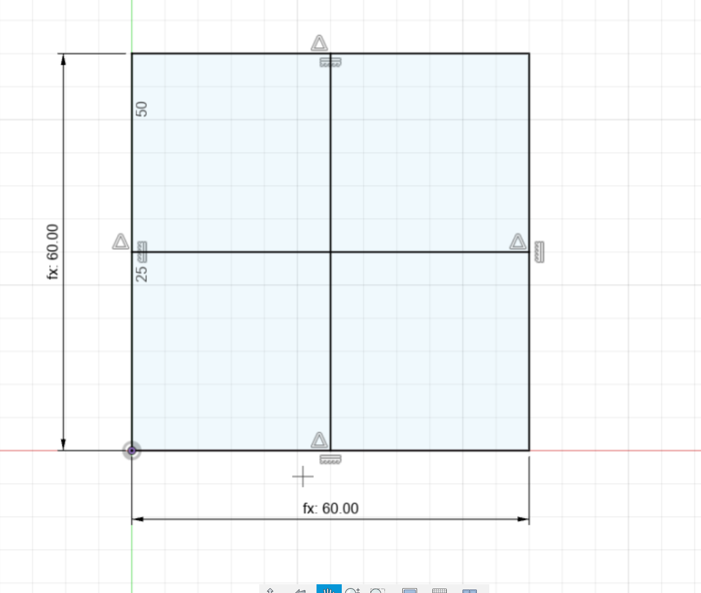
I’ll then draw a circle with the center at the intersection of these lines. I’ll turn both the circle and the intersection lines to construction lines using the sketch palette. This ensures they won’t interfere with my original extrusion operation
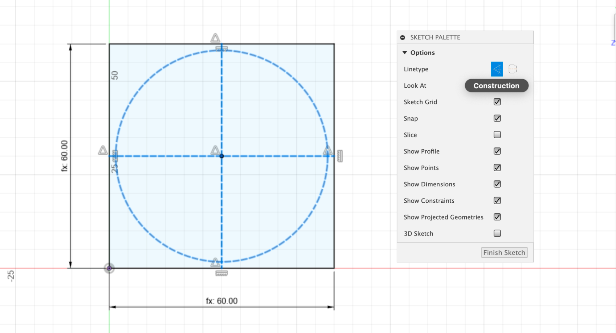
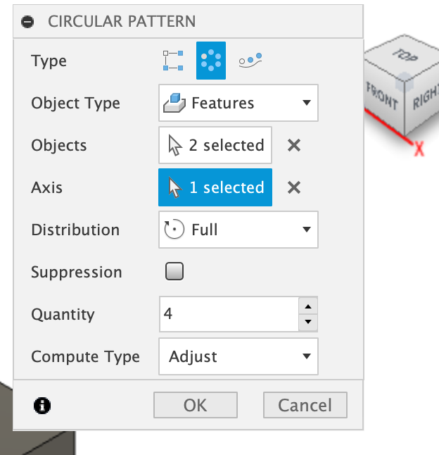
I’ll exit the sketch and create a second pattern operation. However, this time, I'll select the circular pattern and set the axis to the circle. I can do this by selecting the circle in the sketch.
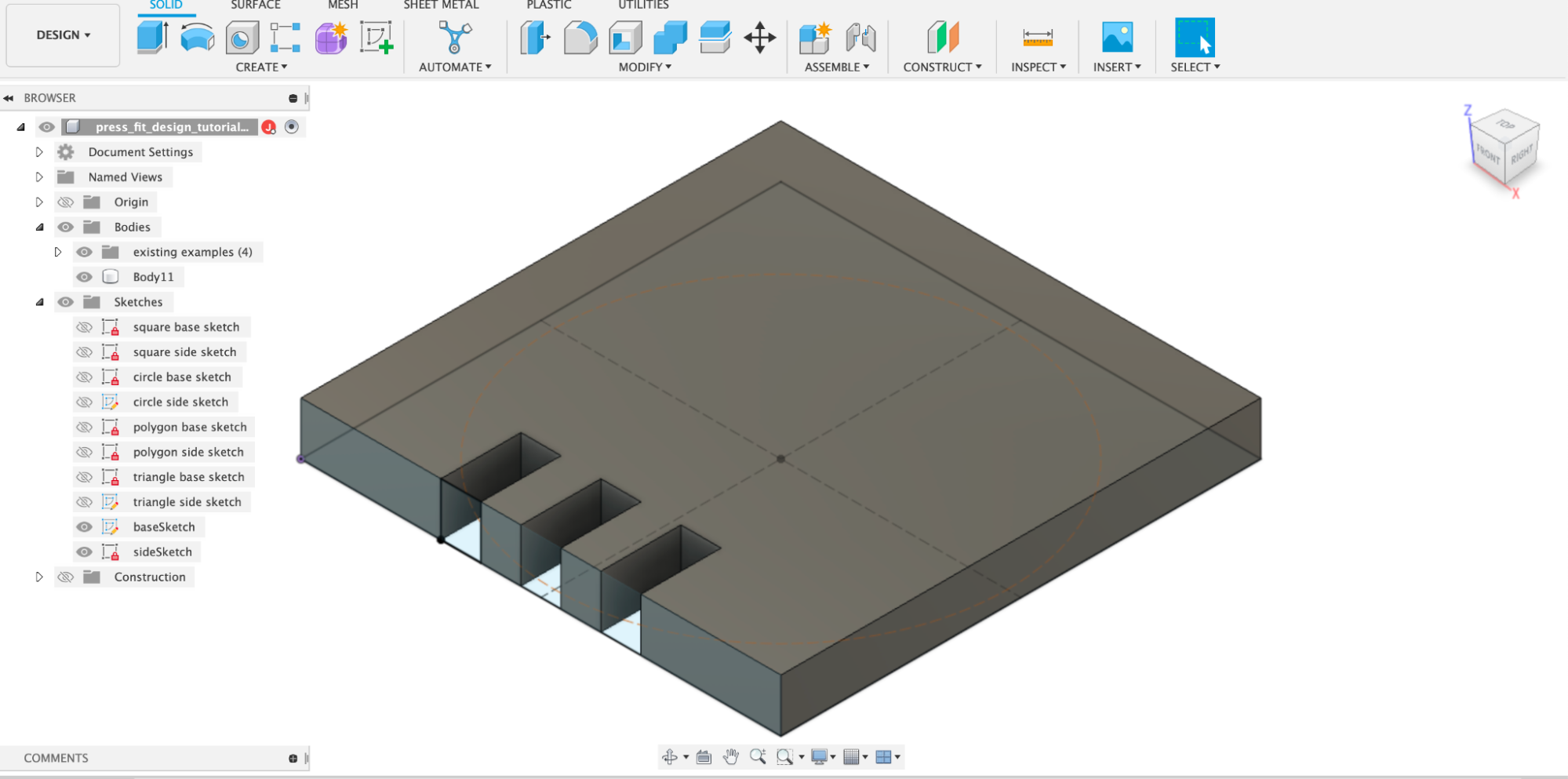
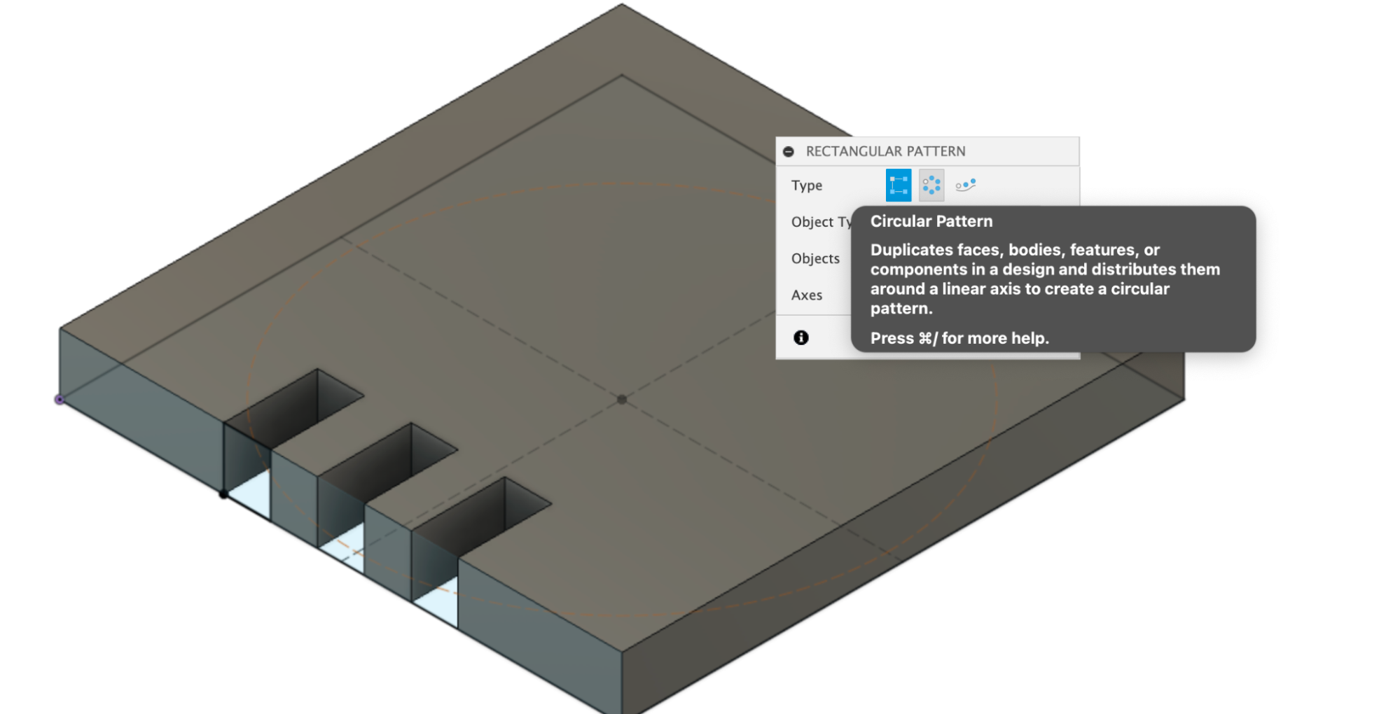
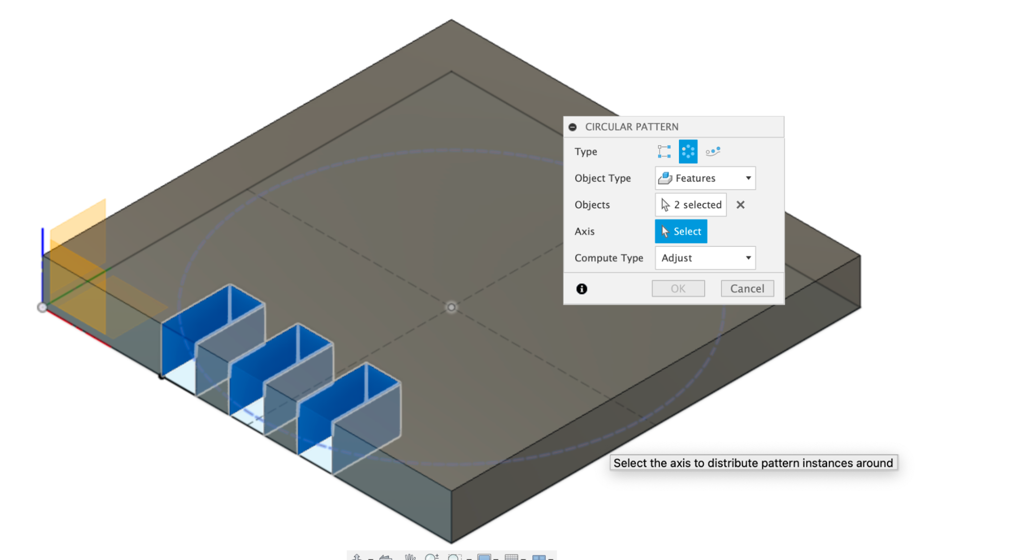
I’ll set the quantity to four and select all the notches on one side. This will create a set of notches on all four sides.
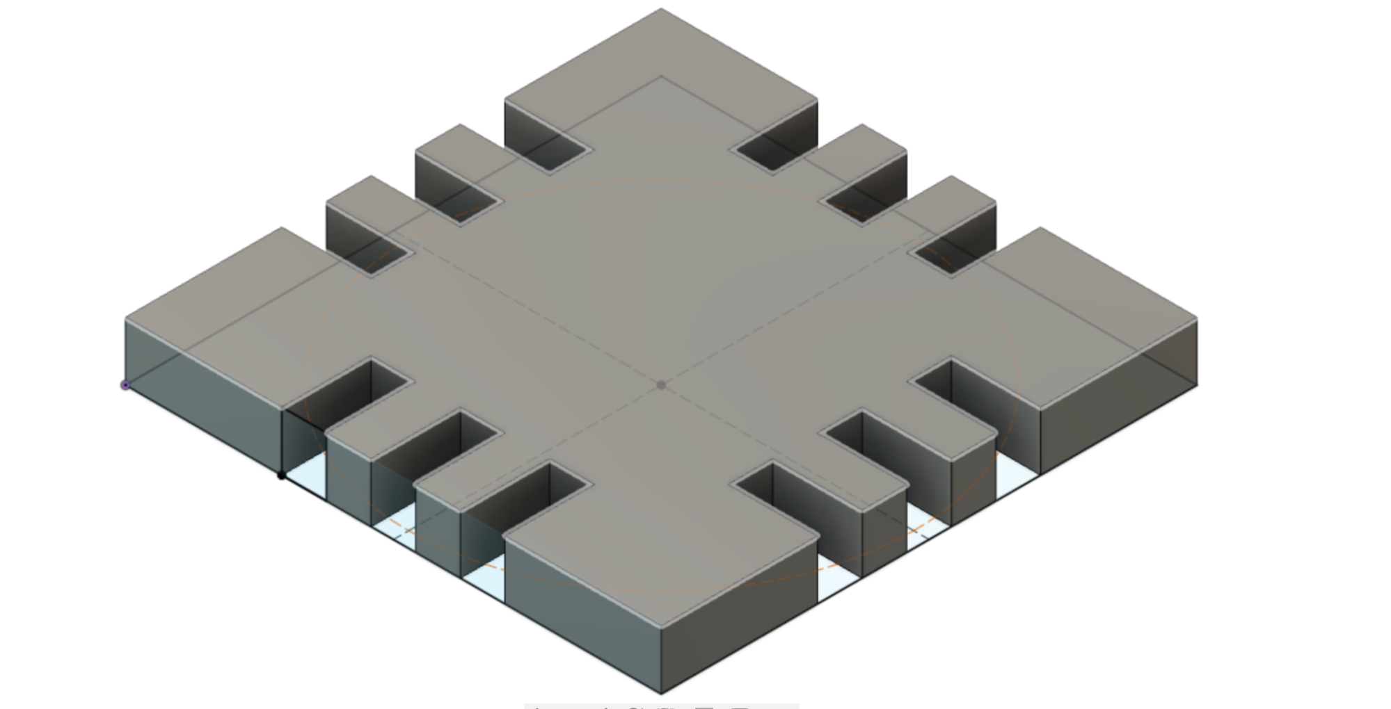
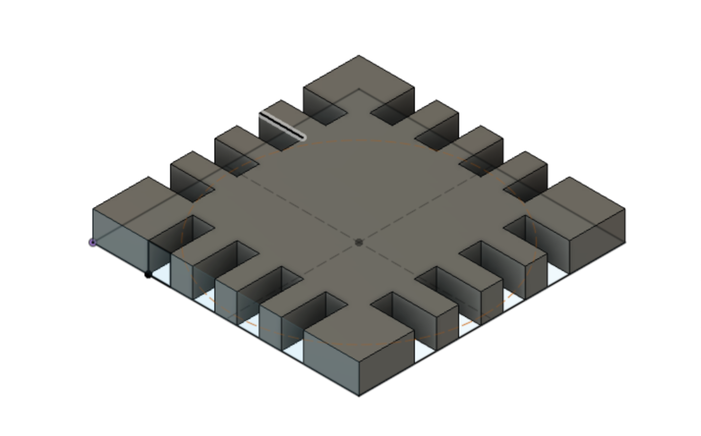
I can adjust the parameters of my design by changing my original user parameters.
To export the design for laser cutting, you have a couple options: Easy Option You can select the original sketch from your design from the Browser menu, right click on it, and select "Export as DXF". This will save a DXF version of the file that preserves the original dimensions of the sketch. This is fast and easy, but does not account for kerf.
Complex Option If you need to account for kerf- e.g. you are doing something with joints or press fit design, you can follow this guide to go through the machining process in Fusion to produce a DXF file that accounts for that parts of the material that the laser cutter will remove. Slides