Intro to Building Custom Modular Interfaces with the Basic Module
Thus far, you've been using the machine module to drive the motors of your machine AND to connect your physical interface elements. This guide introduces the process of adding a Basic Module:
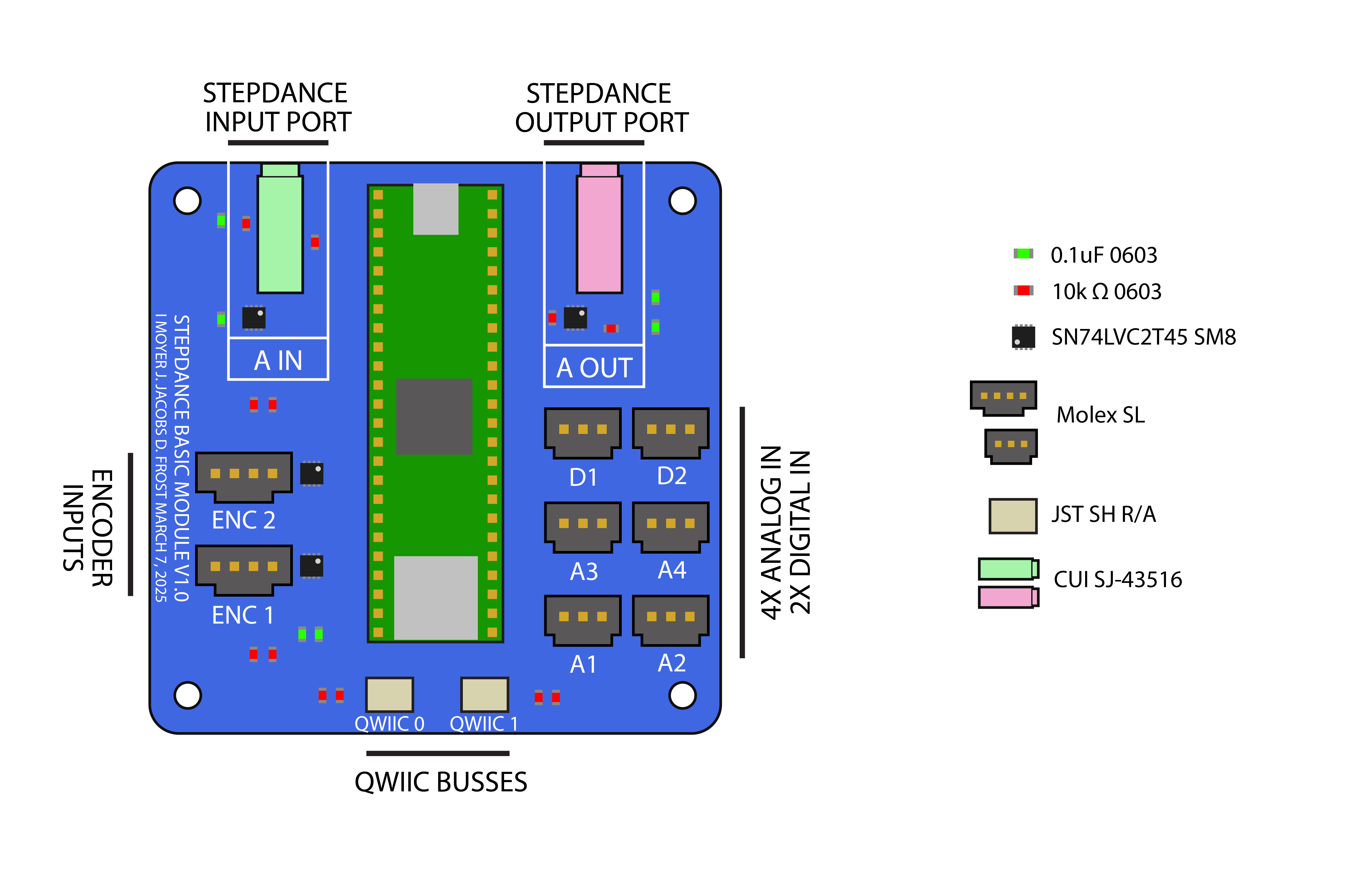
The Basic Module is a a stripped-down version of the Driver Module. It has:
- 2 encoder ports
- 4 analog/digital inputs A1->A4, which also can be digital outputs
- 2 digital inputs/outputs D1->D2
- 2 QWIIC connectors
- 1 stepdance input port
- 1 stepdance output port
Why a basic module?
The module is designed for rapid prototyping new interfaces and must be chained to a driver module via its output port to set For more technical specs and dimensions refer to Basic Module v1.0.
You can chain together multiple modules in sequence including both Basic and Machine Controller Modules. This lets you:
- extend the number of interface peripherals available to you (e.g. more ports)
- combine multiple interfaces with the same machine controller module.
- Rapidly swap out different interfaces
- Use lower cost modules (e.g. Basic Module) for extending a higher cost module (e.g. Driver Module)
Setting up Module Hardware and Software
The hardware setup process for adding input peripherals (encoders, sliders, buttons, etc.) or setting up generators is identical to the machine controller board. All connectors and voltage requirements are the same. The process of programming these components in software is also almost identical. There are two primary changes.
- At the very start of your program you must tell the software that you are programming a basic module, rather than a driver module.
#define module_basic // tells compiler we're using the Stepdance Driver Module PCB
This statement should replace the #define module_driver statement you have previously been using when programming the machine driver modules.
- You must program the module to send the motion signals it generates to downstream modules (e.g. the Driver Module usually or another Basic Module (possibly, but probably not necessary for most projects)). To do this you must define and initialize the module's
OutputPort. The OutputPort is a software component that corresponds to the red (or pink-ish) audio jack connector on the board. We set it up in software as follows:
// -- Define Output Ports --
OutputPort output_a; // all stepdance modules have one output port

void setup() {

    // -- Configure and start the output ports --
  output_a.begin(OUTPUT_A);

}
You then need to map whatever components that generate motion streams to stream to the output port. This is best achieved by mapping those components to a channel that has the output port as its target. This is identical to how you were previously connecting channels to motor driver output ports on the Driver Module. The code below demonstrates streaming the signal generated by an encoder to the output port A.
// -- Define Output Ports --
OutputPort output_a; // all stepdance modules have one output port

// -- Define Motion Channel --
Channel channel_x;

// -- Define Encoders --
Encoder encoder_x; //ENC_1 -- x value encoder

void setup() {

    // -- Configure and start the output ports --
  output_a.begin(OUTPUT_A);

  // -- Configure and start the channels --
  channel_x.begin(&output_a, SIGNAL_X); // channel is registered with the basic module output port on SIGNAL X
  channel_x.set_ratio(0.01, 1); //basic resolution of 1 output step = 0.01mm

  encoder_x.begin(ENCODER_1); // X ENCODER
  encoder_x.set_ratio(TWO_PI, 40000); // 1 REV = 40000 COUNTS. (10K Cycles/Rev)
  encoder_x.output.map(&channel_x.input_target_position, ABSOLUTE);
}
You might notice that a basic module can generate multiple motion streams but only has one ouput port. How then, do we stream multiple signals to the machine controller?
Each Output and Input Port on the stepdance board is set up with a signaling scheme that can transmit up to 4 channels of motion simultaneously! We achieve this with pulse width modulation- for specific details see the Stepdance Electrical documentation.
To achieve this in practice, you just need to change the signal parameter for each channel mapping. For example the following shows mapping for different channels to the same output port with four different signals. The channel names don't have to match the signal names, but you are restricted to mapping to either SIGNAL_X,SIGNAL_Y,SIGNAL_Z, or SIGNAL_E.
channel_x.begin(&output_a, SIGNAL_X); // channel is registered with the basic module output port on SIGNAL X
channel_y.begin(&output_a, SIGNAL_Y); // channel is registered with the basic module output port on SIGNAL Y
channel_z.begin(&output_a, SIGNAL_Z); // channel is registered with the basic module output port on SIGNAL Z
channel_e.begin(&output_a, SIGNAL_E); // channel is registered with the basic module output port on SIGNAL E
Setting up the Machine Controller Module to receive Motion Streams from Basic Modules
The last thing you need to do is set up your machine driver module to receive motion streams from upstream modules. To achieve this, you initialize an input port which corresponds with one of the four physical green input ports on the Driver Module. This example shows setting up and mapping multiple signals of an input port to a channel, but you could also map them to kinematics components, generator parameters, or any other mappable components.
// -- Define Input Ports --
InputPort input_a;

void setup() {
  // -- Configure and start the input ports --
  input_a.begin(INPUT_A); // for a machine controller the parameter for input.begin should correspond with the physical port letter (A-D). Inputs can still receive up to four different signals of motion streams on the machine controller, there's just more of them physically as well.
  input_a.output_x.set_ratio(0.01, 1); //1 step is 0.01mm - this should probably match the mapping from your upstream output
  input_a.output_x.map(&channel_x.input_target_position);

  input_a.output_y.set_ratio(0.01, 1); //1 step is 0.01mm
  input_a.output_y.map(&channel_y.input_target_position);

}
Once you've got your boards programmed, the next step is attach the output of the Basic Module (red) to the correct input of the downstream module (green) and THEN power on your boards. Note that you only need to power the teensy on one of the chained boards. The audio cables will transmit power across them. You should not have micro usbs plugged into more than one teensy.
The physical input and output ports are NOT hot swappable, meaning that if you unplug and plug them in while your board is powered either by the external power supply or the usb cable, you could short the board. Please remember to unplug your boards from power before chaining or un-chaining them!