Intro to generators
In the Step-a-sketch machine, we mapped the motion signal from the encoders to the motion of the stepper motors. In this tutorial we will look at ways to generate motion signal from code. We will also see that we can combine different sources of signal to create more complex motion.
Setup
- Use the same hardware setup as the previous example (Axidraw + encoders + button + Stepdance board)
- Open the Arduino sketch
lib/examples/cmc_cours/02_intro_to_generatorsin Arduino IDE. This sketch starts up nearly identical to the code for the Step-a-sketch example, we will build on it to play with different kinds of generators. - In this tutorial we will be using the Serial Monitor to send commands to the board over USB Serial, from section 2 onwards. Make sure that your Serial Monitor panel is open in Arduino IDE (if not open it with
Tools > Serial Monitor). - After uploading the sketch to the board, you should be able to send and receive messages to the board over serial. Test that the connection works by sending the following JSON message and making sure you receive a reply (see image below):
{"name": "hello"}
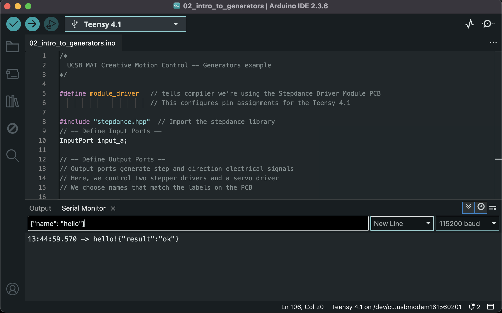
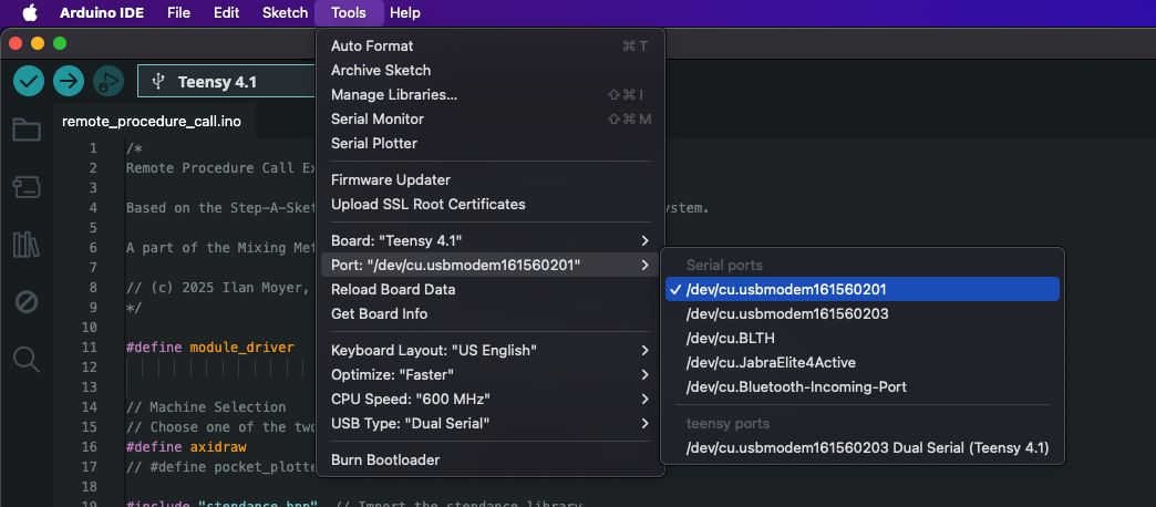
If you are receiving no reply from the board, verify which port is selected in Tools > Port. Try to switch ports, and select a port under Serial ports
This syntax {"name": <method name>, "args": <list of args>} is the syntax that we use to trigger methods on the embedded program through serial messages. You will see it again a lot in the following guide.
1. Position generator: raise and lower pen
The position generator is already used in this example to control the motion of the servo motor responsible for raising and lowering the pen. Here are the code excerpts responsible for the behavior of the position generator:
// -- Position Generator for Pen Up/Down --
PositionGenerator position_gen; // declares the PositionGenerator object

void setup() {

  //...

  // -- Configure Position Generator --
  // map the signal generated by position_gen to the Z channel (pen servo)
  position_gen.output.map(&channel_z.input_target_position);
  // any plugin must call begin
  position_gen.begin();

  // -- Configure Button --
  button_d1.begin(IO_D1, INPUT_PULLDOWN);
  button_d1.set_mode(BUTTON_MODE_TOGGLE);
  button_d1.set_callback_on_press(&pen_up);     // when pressing the button, call pen_up method
  button_d1.set_callback_on_release(&pen_down); // when pressing the button again, call pen_down method

}

void pen_down(){
  // Generate motion at speed 100 units/s, until the position -4 is reached
  position_gen.go(-4, ABSOLUTE, 100);
}

void pen_up(){
  // Generate motion at speed 100 units/s, until the position 4 is reached
  position_gen.go(4, ABSOLUTE, 100);
}
The position generator acts on a value, that always starts at 0 when the system starts. Upon calling go(target, ABSOLUTE, s), the position generator will gradually increment its value with speed s, until the value reaches specified value target.
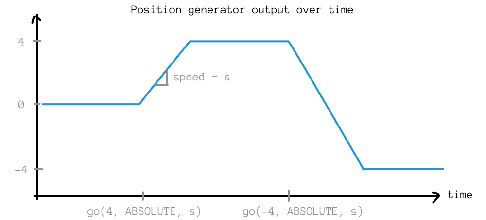
By calling:
position_gen.output.map(&channel_z.input_target_position);
we map the value controlled by the position generator to the position that the Z axis (controlled through channel_z and ultimately the servo motor) is following. So whenever we call go(...) the servo motor rotates and the pen goes up or down.
See the PositionGenerator class documentation for more details.
2. Velocity generator: replace one or both of the encoders by a continuous motion
In this step we will look at how to generate motion on the X and Y axes too.
This will allow us to make the pen move on the page without turning the encoders by hand.
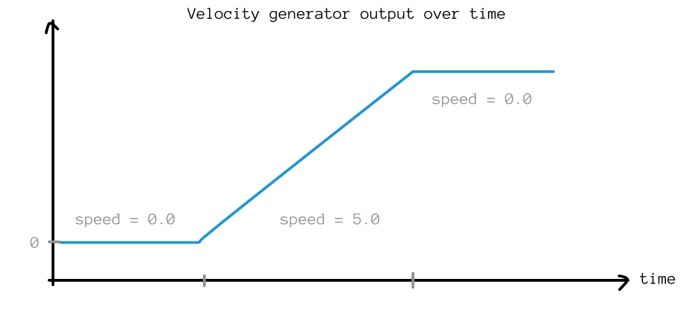
We will use a VelocityGenerator. We provide this generator a speed parameter, and it will continuously increment its internal value over time at this specified speed.
We start by declaring the velocity generator object:
// -- Velocity Generator --
VelocityGenerator vertical_velocity_gen;
Then, in the setup() method, we will configure the generator by providing it with a speed value (let's give it 0 initially) and by mapping the value it controls to the axis that we want to control (let's say the Y axis):
void setup() {
  //...

  // -- Configure the velocity generator --
  // Set the speed (start at zero, use Serial commands to change it, or change the value in code)
  vertical_velocity_gen.begin(); // all plugins must call begin
  vertical_velocity_gen.speed_units_per_sec = 0.0;
  // Control the motion in Y axis with the velocity generator
  vertical_velocity_gen.output.map(&axidraw_kinematics.input_y);
}
Currently, the velocity generator wouldn't do anything, because its speed is set to zero. We will make it so that we can control the generator's speed through serial commands. The Arduino sketch provided to you already exposes functions that can be called through serial, all that's left to do is to indicate what to do when the function is called.
For setting the vertical velocity generator speed, modify the set_speed_y function like so:
void set_speed_y(float32_t speed){
  vertical_velocity_gen.speed_units_per_sec = speed;
}
The unit of speed is in mm/s movement along the vertical axis.
Remember that the Axidraw will not stop moving to prevent itself from crashing into its limits. Help yourself avoid these collisions by starting all tests from a "neutral" start position. Before anything, manually move your Axidraw's axes, to place the pen roughly in the center of its reachable area. That way, the axes start far away from the places where they would collide.
The Axidraw's axes can be moved manually when the stepper motors are not powered, for instance you can unplug the USB cable from your laptop.
The code is all setup! Next upload the sketch to the Teensy, and open the Serial Monitor. Once the sketch is uploaded, send the following command through serial:
{"name": "set_speed_y", "args": [5]}
You should see the Axidraw start slowly moving the pen along the vertical axis.
To stop this motion, set the velocity generator's speed to zero again with the following serial command:
{"name": "set_speed_y", "args": [0]}
Another way to quickly stop the Axidraw is to simply unplug the Stepdance board from power, for instance unplugging your USB cable connection. Re-plugging the board restarts the sketch from the beginning, so you lose any state that you had before (e.g., the velocity generator will have its speed reset to 0).
Now you can play with setting different speeds (try a negative value, try a larger or smaller value), and you can also move the encoders to combine the velocity generator motion with the motion signal from the encoders.
Optional step: can you add a second velocity generator to control the horizontal motion?
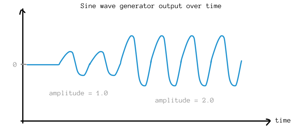
3. Sine wave generator: bobbing pen
Motion generators can get more complex: we can effectively generate signals following any scalar function. In this example we will generate a sinusoidal wave and map it to the Z axis, to make the pen bob up and down. To do so, we will use a WaveGenerator1D.
First, declare the generator:
// -- Wave Generator --
WaveGenerator1D z_wave_gen;
Then, initialize the generator:
void setup() {
  //...

  // -- Configure the wave generator --
  z_wave_gen.setNoInput();     // we will use the internal clock as the time variable
  z_wave_gen.frequency = 10.0; // frequency of oscillation (feel free to change)
  z_wave_gen.amplitude = 0.0;  // amplitude of the wave (start at 0, change through serial)
  // We map the wave signal to the Z channel
  z_wave_gen.output.map(&channel_z.input_target_position);
  z_wave_gen.begin();
}
Just like for the velocity generator, we will control the wave amplitude through serial. Modify the following function so that serial commands affect the wave's amplitude:
void set_z_amplitude(float32_t amplitude){
  z_wave_gen.amplitude = amplitude;
}
Time to deploy and test. This time, use the following serial command:
{"name": "set_z_amplitude", "args": [4]}
And play with the amplitude value. Note that you can also move the plotter in XY using either the encoders or the velocity generator. Try to draw a regular dotted line with the plotter.
4. Circle generator: generating motion for multiple axes
Lastly, we will see that a generator can be setup to feed motion signals to multiple axes at the same time. Consider the following two motion signals:
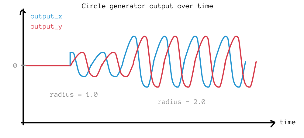
If we pass the cosine function (blue) to the X axis, and the sine function (red) to the Y axis, we will draw circles. This is what the CircleGenerator implements.
Let's add it:
// -- Circle Generator --
CircleGenerator circle_gen;
// -- Circle Generator --
void setup() {
  //...

  // -- Configure the circle generator --
  circle_gen.radius = 0.0;
  circle_gen.rotational_speed_rev_per_sec = 10.0;
  circle_gen.setNoInput(); // we will use the internal clock as the time variable

  // Map circle outputs to X and Y channels
  circle_gen.output_x.map(&axidraw_kinematics.input_x);
  circle_gen.output_y.map(&axidraw_kinematics.input_y);
  circle_gen.begin();
}
void set_circle_radius(float32_t radius){
  circle_gen.radius = radius;
}
Now, if you set the radius to some non-zero value:
{"name": "set_circle_radius", "args": [1]}
you should see the Axidraw moving in circles.
Throughout the course of this tutorial, we have mapped multiple signals to axidraw_kinematics.input_x and axidraw_kinematics.input_y. Doing so mixes the signals by adding them to one another. For instance, we can now move along the X axis by turning the encoder, while at the same time drawing loops -- the signals get added together.
Going further
But how do generators work? How would I make my own generator if I wanted to?
Generators are part of the Stepdance library code, you can go inspect the source code on Github or by looking in your local clone at stepdance/lib/generators.cpp, to see how they work. The meat of the logic in generators is in their run() method, which is what gets called by the Stepdance main loop at every frame.