Understanding Stepdance Motion Streams
Traditional CNC machine controllers convert precompiled G-code instructions to step and direction pulses which are then transmited to machine motors to This signaling contains real-time position and velocity data; however, G-code controllers do not typically expose these signals.
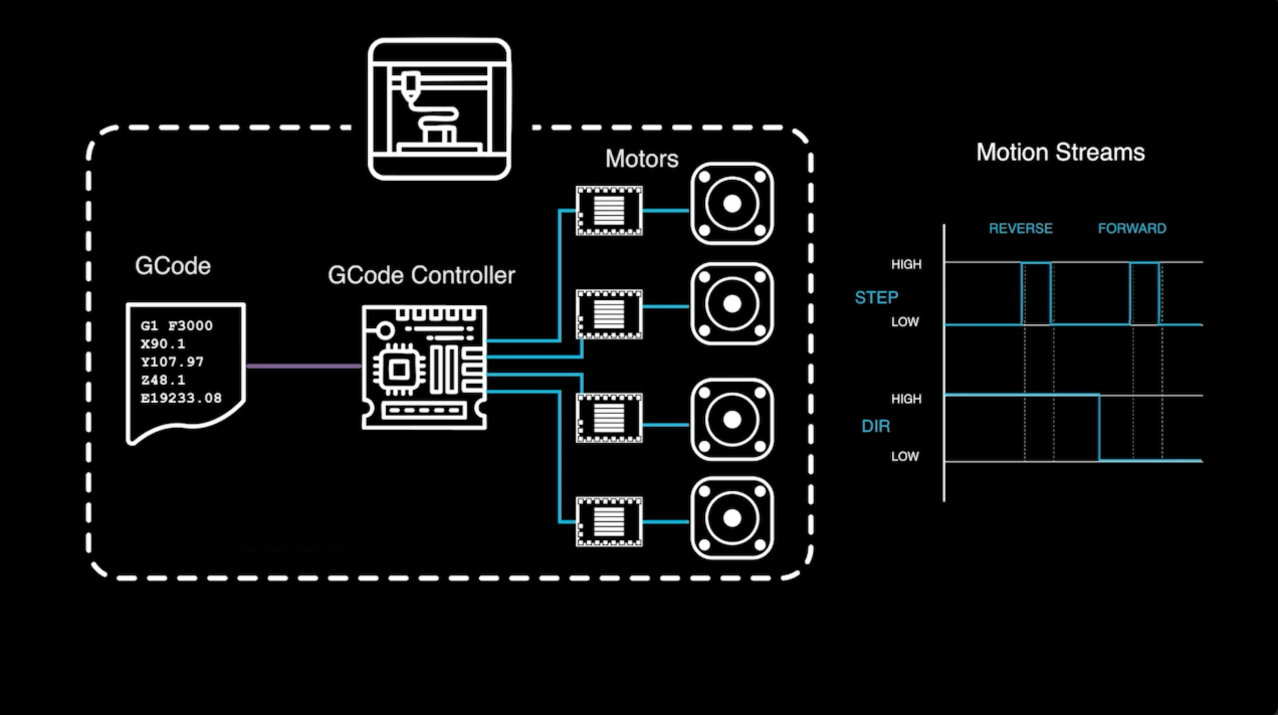
Stepdance exposes step and direction as first class data types which can be generated, transmitted and modified by different software components and then passed to motors. This guide walks through the basics of controlling motion streams using the example referenced in the step-a-sketch guide.
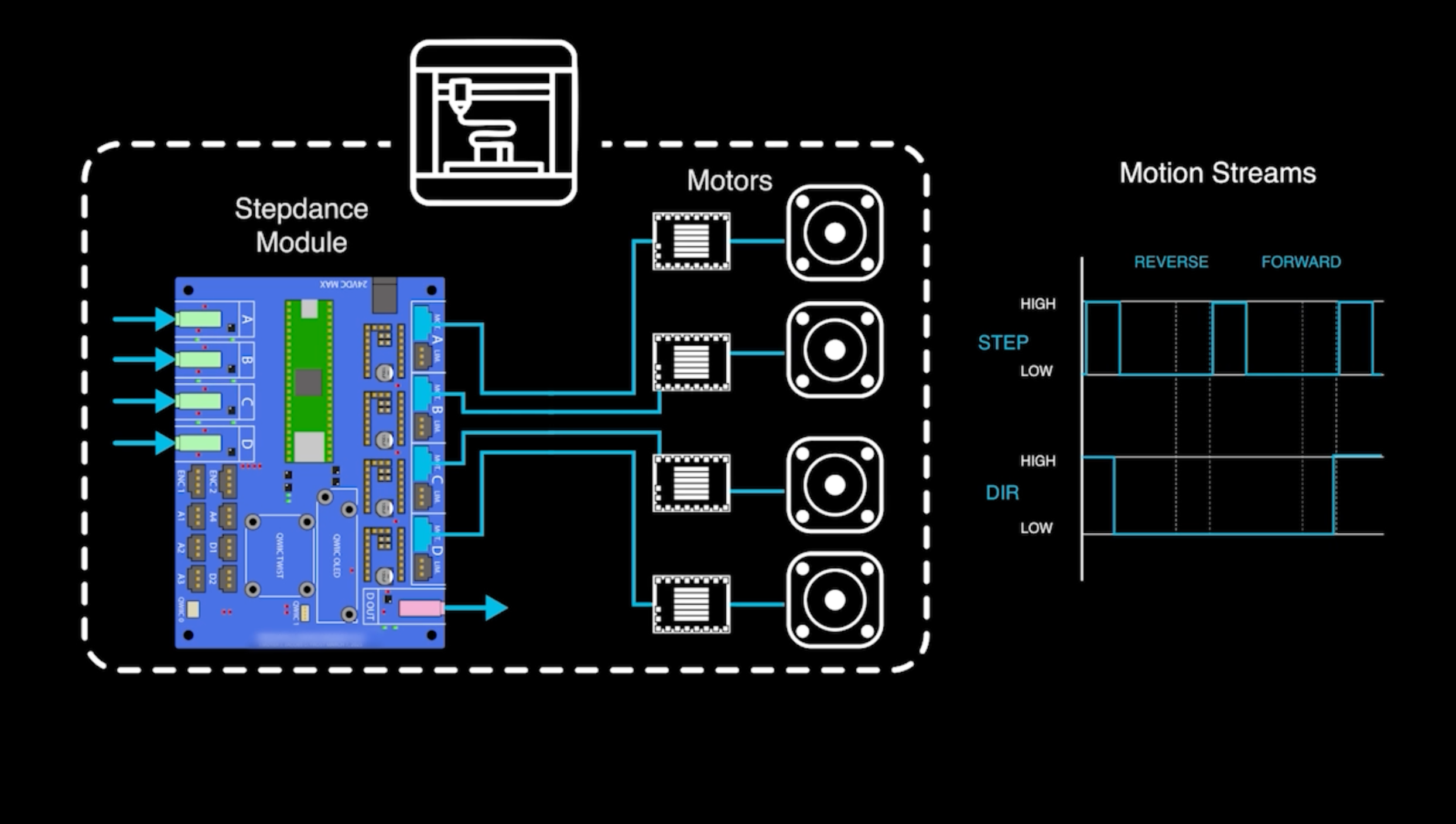
Step-a-Sketch Program Flow:
Stepdance programming is inspired by metaphor of audio modular synthesizers. In a modular synthesizer, audio signals that is transmitted across different modules that can generate, filter, and output audio in different ways.
Stepdance programming is similar, except instead of transmitting audio signals between modules, we are transmitting motion in the form of motion streams. The mappings between different components are automatically maintained and updated (for the most part) by the SSL dance_loop() function.
You can think of Stepdance programming as somewhat similar to Max or other dataflow languages, except it is textual, not visual.
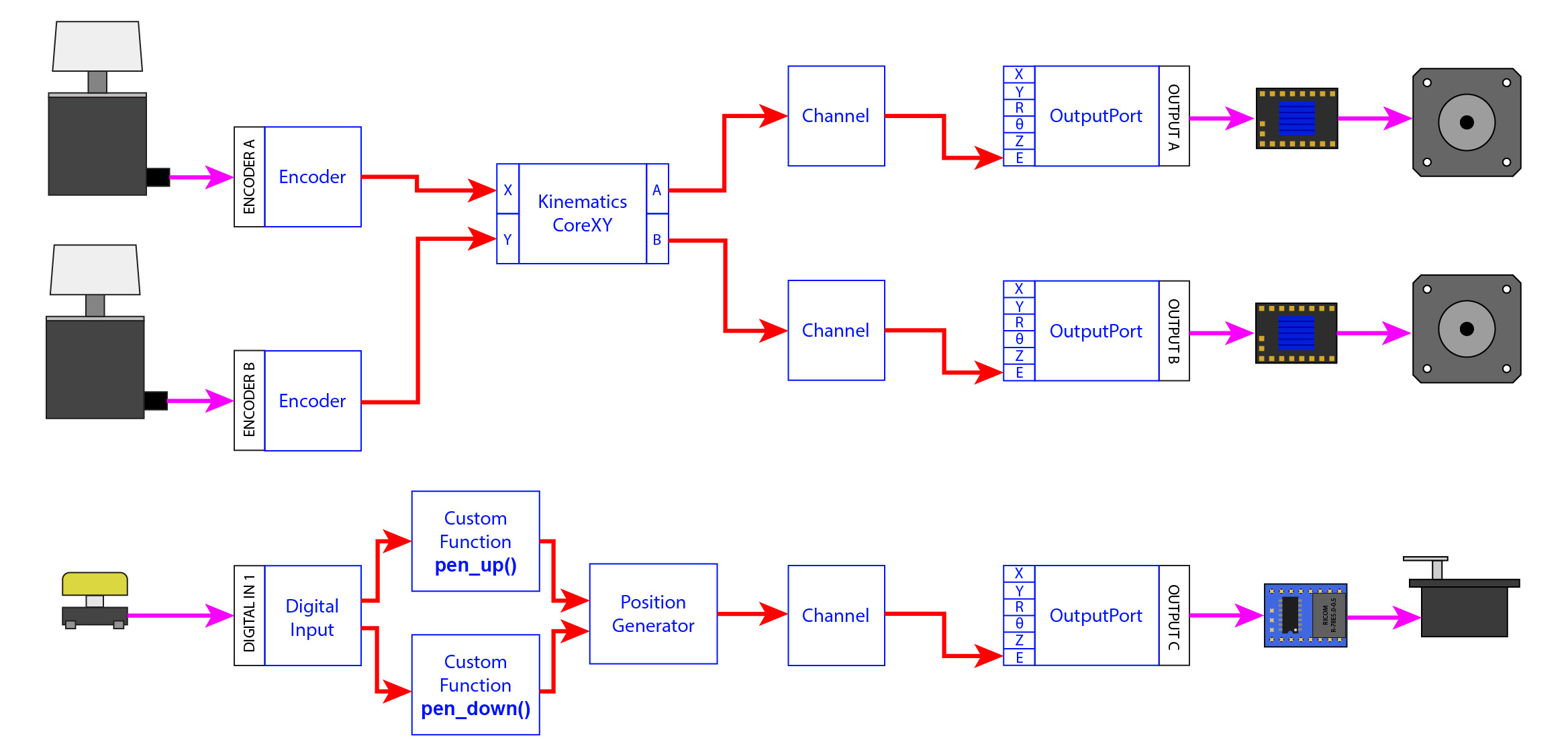
This diagram shows the entire program flow for the Step-a-Sketch. We'll walk through each SSL component from right to left. (SSL) components are the blue boxes consisting of red arrows. Some but not all SSL components correspond to physical ports on the Stepdance Machine Driver board.
The full program source code demonstrated in class is on github as an example in the stepdance library: github/01_motion_streams_demo Note that this example just covers mapping an encoder to a single motor, without kinematics. For kinematics see the step_a_sketch guide.
Arduino Program Setup
We build from the Arduino C++ programming schema. The SSL is an Arduino IDE-compatible library. For all SSL programs you must first define the board type and import the SSL library. You then define all components prior to the setup function, and call dance_loop() within the arduino loop function to automatically update your mappings
#define module_driver //specify the type of stepdance board you are programming
#include "stepdance.hpp" //include the stepdance library

//DEFINE YOUR COMPONENTS BEFORE SETUP

void setup() {
//INITIALIZE AND MAP COMPONENTS WITHIN SETUP FUNCTION

dance_start() // needs to be called at the end of setup to initialize all of the components.
}

void loop(){
//CALL DANCE LOOP TO AUTOMATICALLY UPDATE STEPDANCE MAPPINGS
dance_loop();
}
OutputPort
- OutputPorts convert internal step commands into movement signals.
- Signals are fed into the motor via the corresponding output port on the Driver board. Here's an example of how to instantiate and configure an OutputPort for the corresponding physical port A on the board. Note that you have to call enable_drivers() once you begin the output port:
OutputPort output_a;

void setup() {
  // -- Configure and start the output port --
  output_a.begin(OUTPUT_A); // "OUTPUT_A" specifies the physical port on the PCB for the output.


  // Enable the output drivers
  enable_drivers();
}
Channel
- The channel stores the motor's current positional state.
- It has a "target" position that can be updated by other modules.
- The machine controller preserves state and manages the homing process.
- It accepts motion streams and ensures they are within velocity limits. Here's an example of how to instantiate and configure a Channel:
Channel channel_a;
OutputPort output_a;

void setup() {
  // -- Configure and start the output port --
  output_a.begin(OUTPUT_A);
    // -- Configure and start the channels --
  channel_a.begin(&output_a, SIGNAL_E); // Connects the channel to the "E" signal on "output_a".
                                        // We choose the "E" signal because it results in a step pulse of 7us,
                                        // which is more than long enough for the driver IC
 channel_a.set_ratio(25.4, 2032); // Sets the input/output transmission ratio for the channel.
                                                // This provides a convenience of converting between input units and motor (micro)steps
                                                // For the axidraw, 25.4mm == 2874 steps
}
Channel.begin() expects a pointer to the target output port. You indicate this by including an & in front of the output_port identifier. This enables the channel to reference the location of the OutputPort object, rather than a direct value. If you do not specify a pointer you will get an intense, but easily addressable error message from the Arduino compiler along the lines of:
error: no matching function for call to 'Channel::begin(OutputPort&, int)'
This just means that Channel.begin() received a parameter value it was not expecting.
For more info on pointers see here.
Kinematics
Kinematics modules convert between coordinate spaces. For example, the AxiDraw uses a CoreXY mechanism, so we use a KinematicsCoreXY object to translate between X/Y coordinates (what we want) and A/B motor positions (what the hardware needs). This allows you to think in terms of X/Y movement, while the kinematics module handles the math to drive the correct motors.
Example:
KinematicsCoreXY axidraw_kinematics;

void setup() {
  // ...existing code...
  // Configure and start the kinematics module
  axidraw_kinematics.begin();
  axidraw_kinematics.output_a.map(&channel_a.input_target_position);
  axidraw_kinematics.output_b.map(&channel_b.input_target_position);
  // ...existing code...
}
More details on the kinematics can be found here
Encoder
Stepdance enables you to connect different Input Devices (buttons, knobs, encoders, pedals, etc.) to your board to control machines. encoders are a type of Input Device. Encoders read quadrature signals, such as from rotary knobs. In this project, two encoders act as the "etch-a-sketch" knobs, controlling X and Y movement. In the final program, each encoder is mapped to the appropriate kinematics input, so turning a knob moves the plotter in X or Y.
Example:
Encoder encoder_1;  // left knob, controls horizontal
Encoder encoder_2;  // right knob, controls vertical

void setup() {
  // ...existing code...
  encoder_1.begin(ENCODER_1);
  encoder_1.set_ratio(24, 2400);  // 24mm per revolution, 2400 pulses per rev
  encoder_1.invert();
  encoder_1.output.map(&axidraw_kinematics.input_x);

  encoder_2.begin(ENCODER_2);
  encoder_2.set_ratio(24, 2400);
  encoder_2.invert();
  encoder_2.output.map(&axidraw_kinematics.input_y);
  // ...existing code...
}
PositionGenerator
While the encoders map corresponding movement of the input to the output motor, sometimes it is useful to have movement that is not a direct mapping- e.g. automatically moving the plotter pen up and down. We use the PositionGenerator to do this by sending position commands to the Z channel. This is triggered by the button (see next section).
What does the map function do?
Stepdance, like other dataflow langauges automatically manages the transfer of motion streams across components. When you call encoder_1.output.map(&axidraw_kinematics.input_x) what you are telling stepdance is that whenever the encoder value changes, that output should automatically be transferred and set to the x input of the axidraw kinematics. This way, we don't have to repeatedly call axidraw_kinematics.input_x = encoder_1.read() every loop. There are some caveats to mapping. Each output or input is limited to one target of their
map(&target) function. If you call encoder_1.output.map(&channel_a.input_target_position) AND encoder_1.output.map(&channel_b.input_target_position) the second mapping will just overwrite the first. This is because Stepdance programs must run entirely in embedded hardware. There are work-arounds to support many-to-many mappings which we will get into later.
Example: `
PositionGenerator position_gen;

void setup() {
  // ...existing code...
  position_gen.output.map(&channel_z.input_target_position);
  position_gen.begin();
  // ...existing code...
}

void pen_down() {
  position_gen.go(-200, ABSOLUTE, 2000); // Move pen down
}

void pen_up() {
  position_gen.go(200, ABSOLUTE, 2000); // Move pen up
}
Button
A button is used to toggle the pen up/down state. The button is set up with callbacks for press and release, which trigger the pen movement via the position generator.
Example:
Button button_d1;

void setup() {
  // ...existing code...
  button_d1.begin(IO_D1, INPUT_PULLDOWN);
  button_d1.set_mode(BUTTON_MODE_TOGGLE);
  button_d1.set_callback_on_press(&pen_down);
  button_d1.set_callback_on_release(&pen_up);
  // ...existing code...
}
Debugging and Serial Output
To monitor your program or debug values in real time, you can use Arduino's Serial.print() functions. This is especially useful for checking sensor readings, encoder values, or CPU usage.
Option 1: print values anywhere in your code or inside a function. This can slow down your code if you are printing a lot:
void loop() {
  // Print the value of a variable
  Serial.print("Analog 1 value: ");
  Serial.println(analog_1.read());
  // ...existing code...
  report_overhead();
}
For Stepdance-specific diagnostics or to avoid overhead, you can print CPU usage and other diagnostics in the report_overhead() function
void report_overhead() {
  Serial.print("Analog 1 value: ");
  Serial.println(analog_1.read());
  Serial.println(stepdance_get_cpu_usage(), 4);
}
Open the Arduino Serial Monitor to view your output.
Explore More: VelocityGenerator and AnalogInput
Stepdance supports many more modular components for creative motion control. Two useful modules to try next are:
- VelocityGenerator: Generate and control velocity streams for smooth, continuous motion.
- AnalogInput: Read analog signals (like potentiometers, sensors, etc.) and map them to motion or other parameters.