Basic Parametric Modeling in Fusion
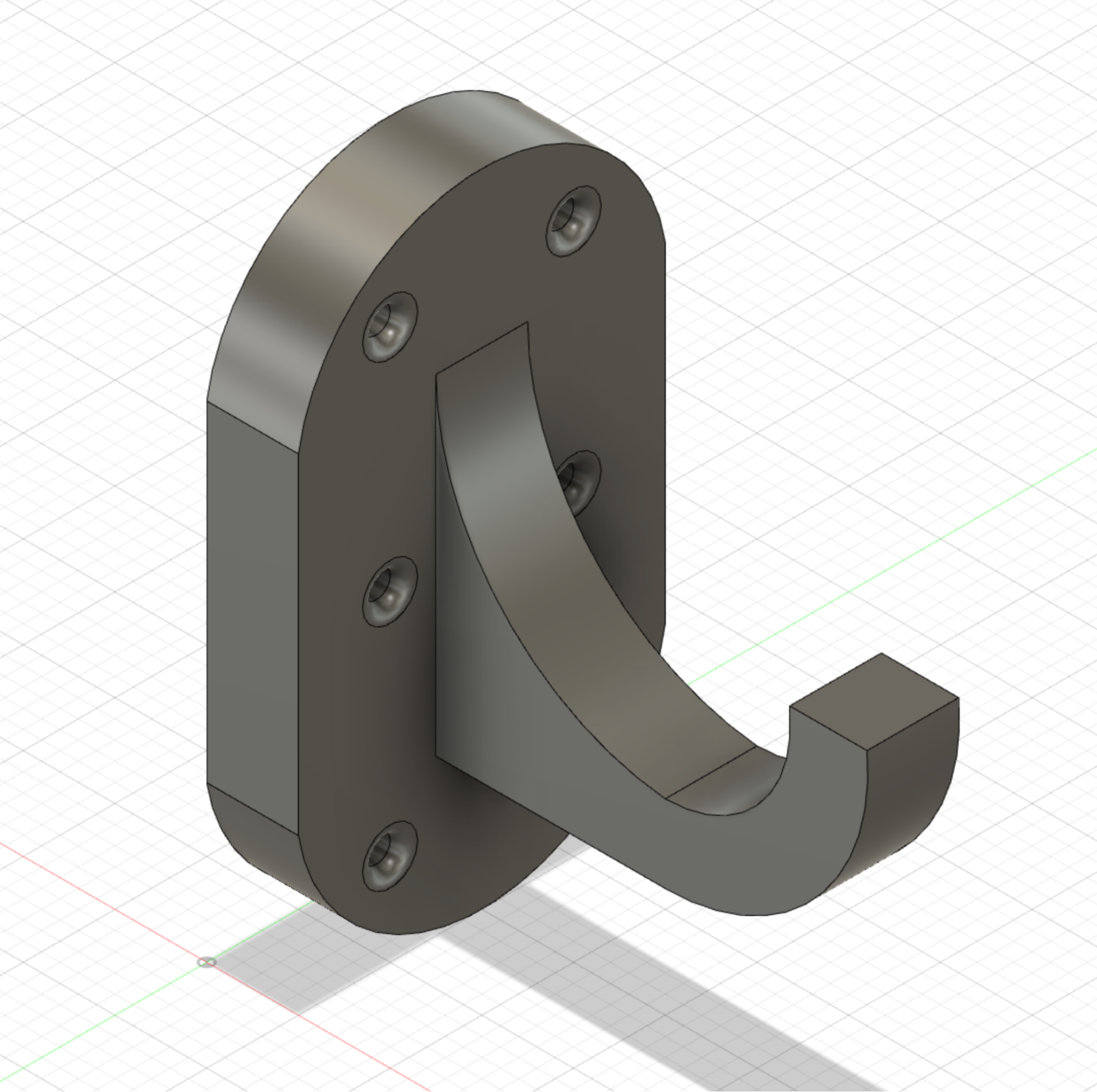
Solid Modeling in Fusion uses a 2D-3D workflow. Designers start by creating a 2D sketch, then move to creating 3D geometry based on features from these sketches. This demonstration walks through modeling a basic bracket with a hook.
Units
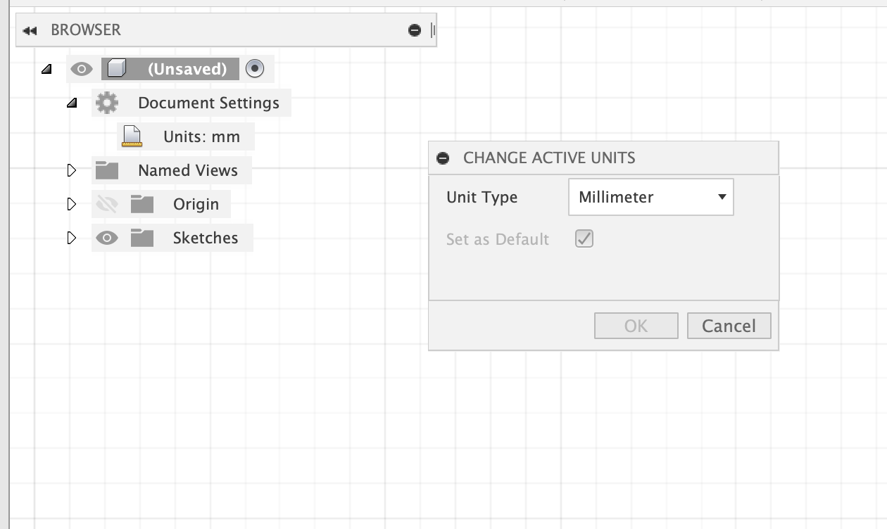
First set your units in the design browser. Under your document, select Units: and change the units to the desired setting. (I prefer inches).
2D Sketching
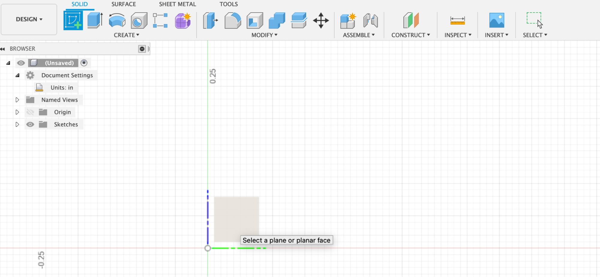
To create a 2D sketch in fusion, select the sketch button from the top horizontal toolbar in the Design Mode:
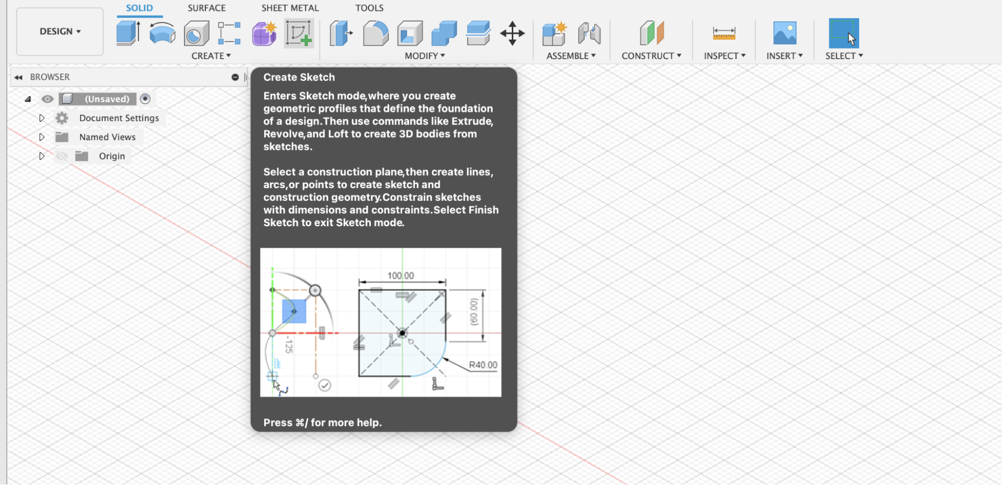
Then select the plane that you want to sketch on. Since we’re creating a hook I’ll select the z-y plane.
The sketching interface provides a range of 2D sketching tools for drawing basic 2D geometry: rectangles, circles, arcs, and lines. Each tool automatically imposes constraints on the drawing. For example, when drawing a rectangle for the start of our mounting bracket for the hook, the rectangle tool automatically creates four edges with horizontal/vertical constraints for the parallel edges, and a constraint on the size of the edges relative to the first corner you place on the canvas.
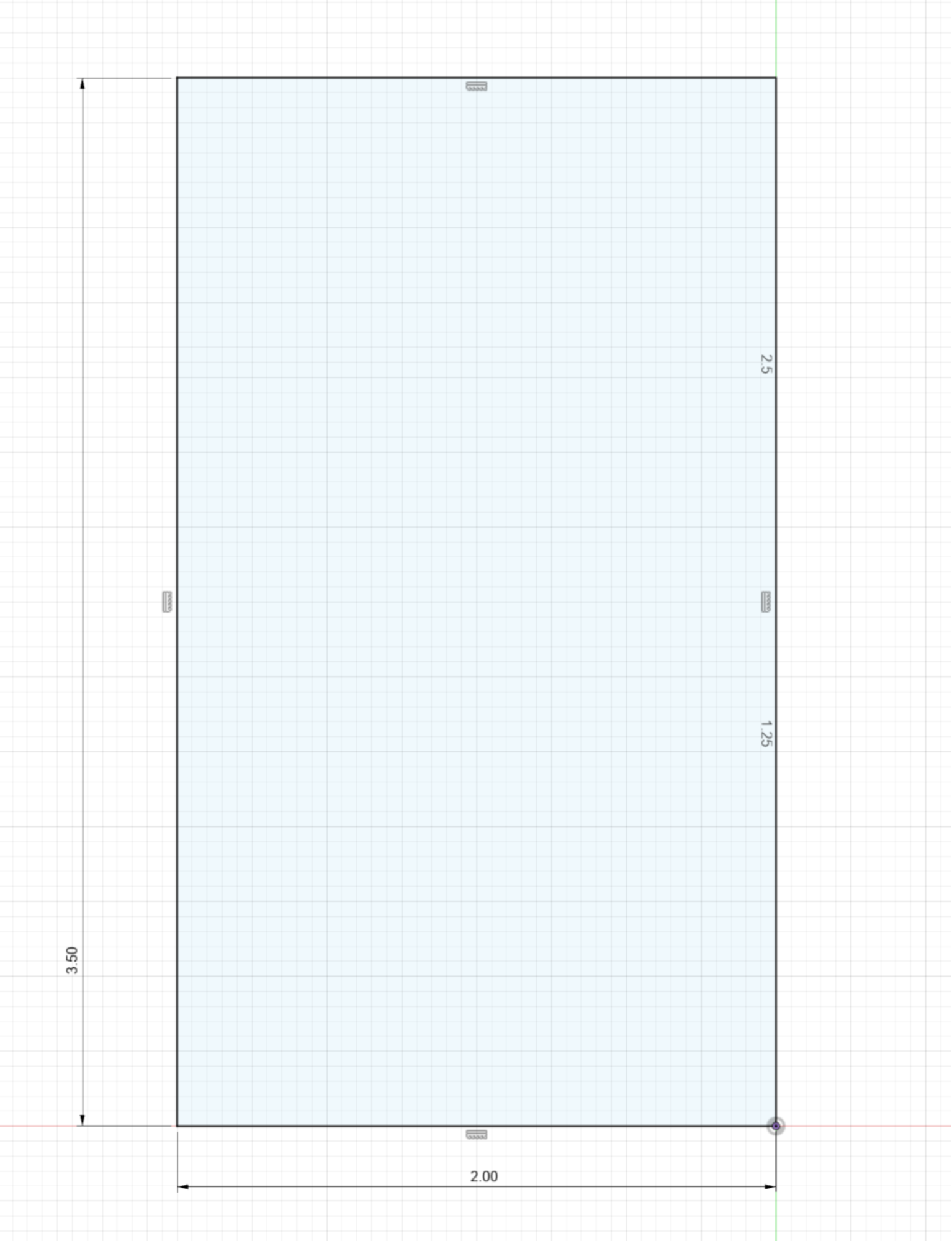
Because of these constraints, drawing requires additional upfront planning in Fusion in comparison to a free-form tool like Rhino.
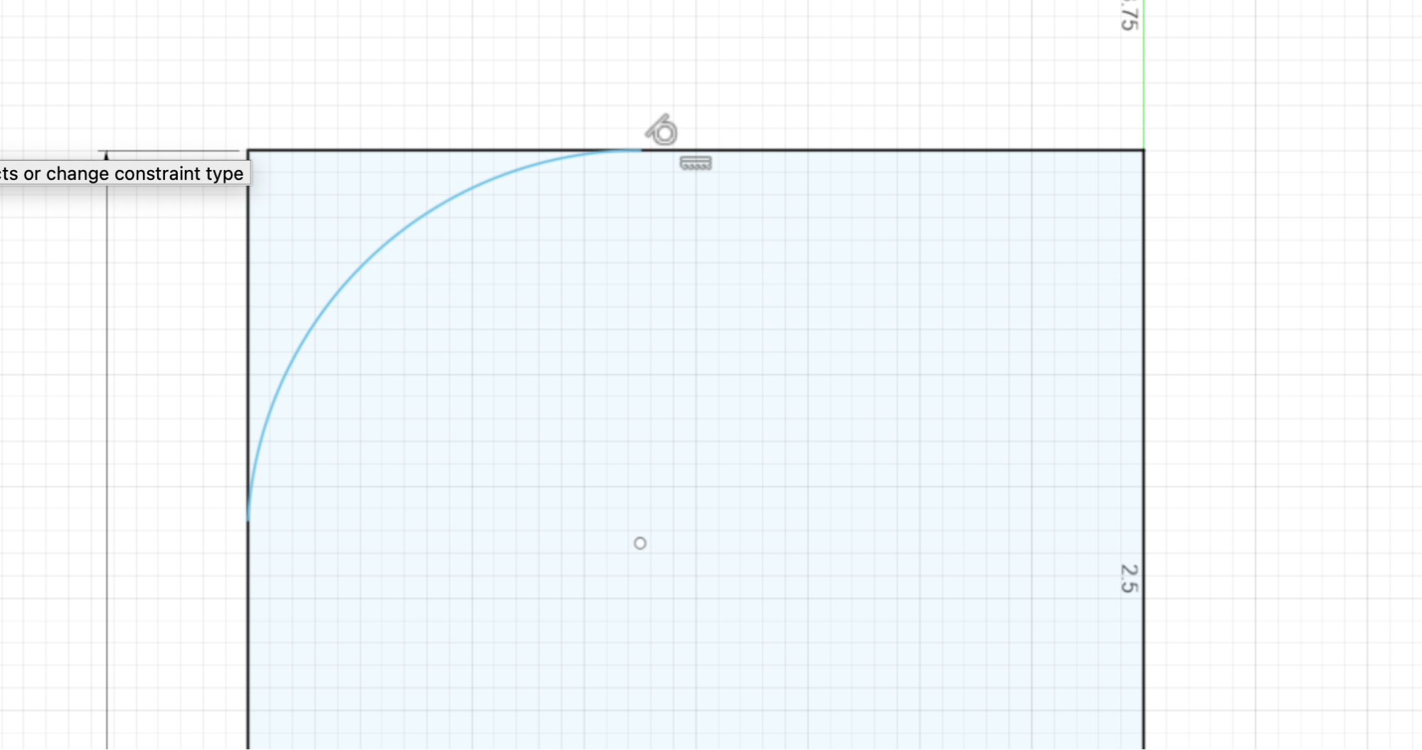
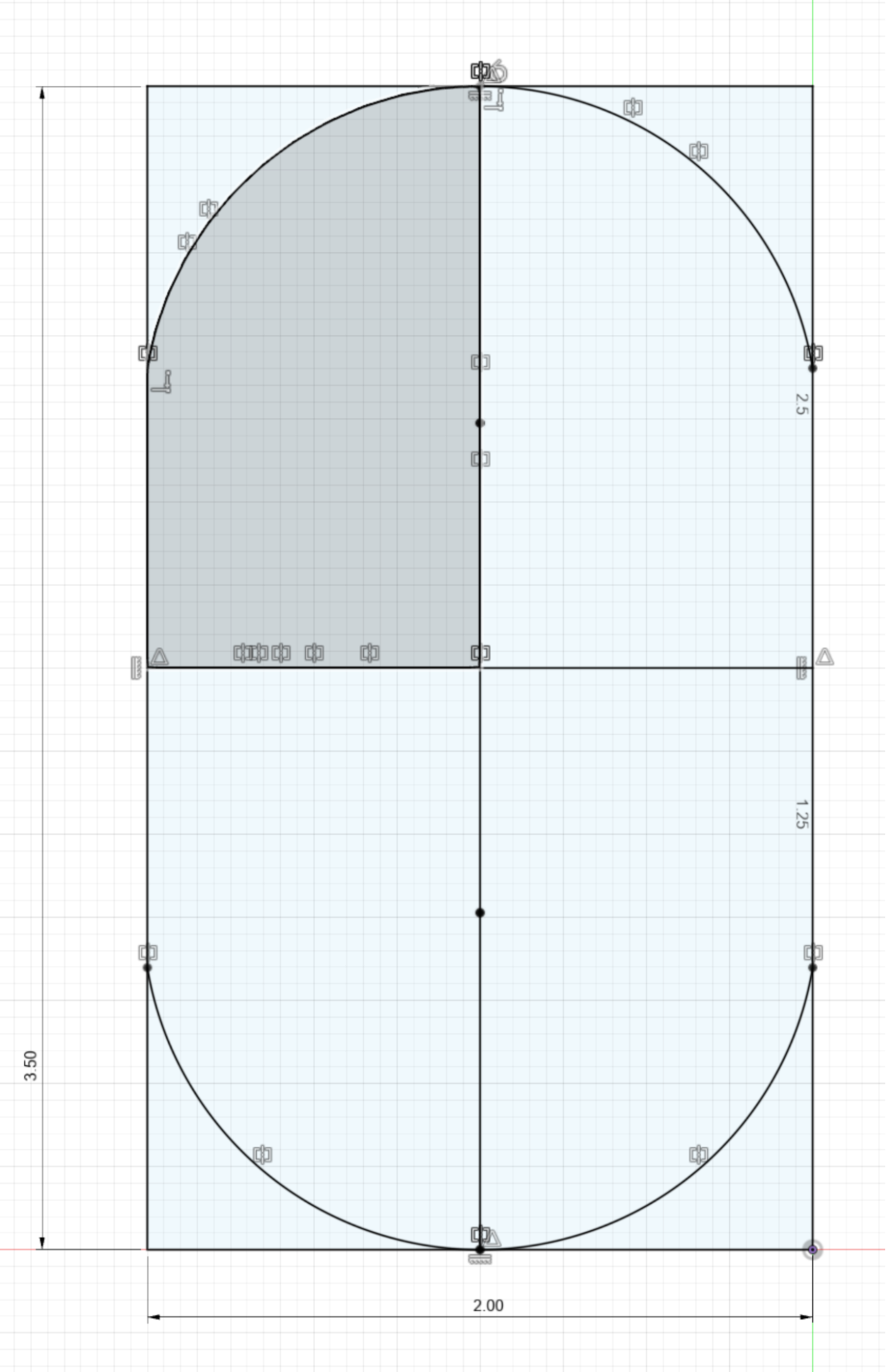
Using the Arc tool, we can create a rounded edge on the rectangle on one corner. Note the tangent constraint that is created with the arc end point and the upper edge of the rectangle.
We can automatically duplicate this geometry to all four corners using the Mirror function. First mirroring the arc on the x axis, and then mirroring both arcs on the y axis. Doing so requires creating two helper lines that split the rectangle at the horizontal and vertical midpoints.
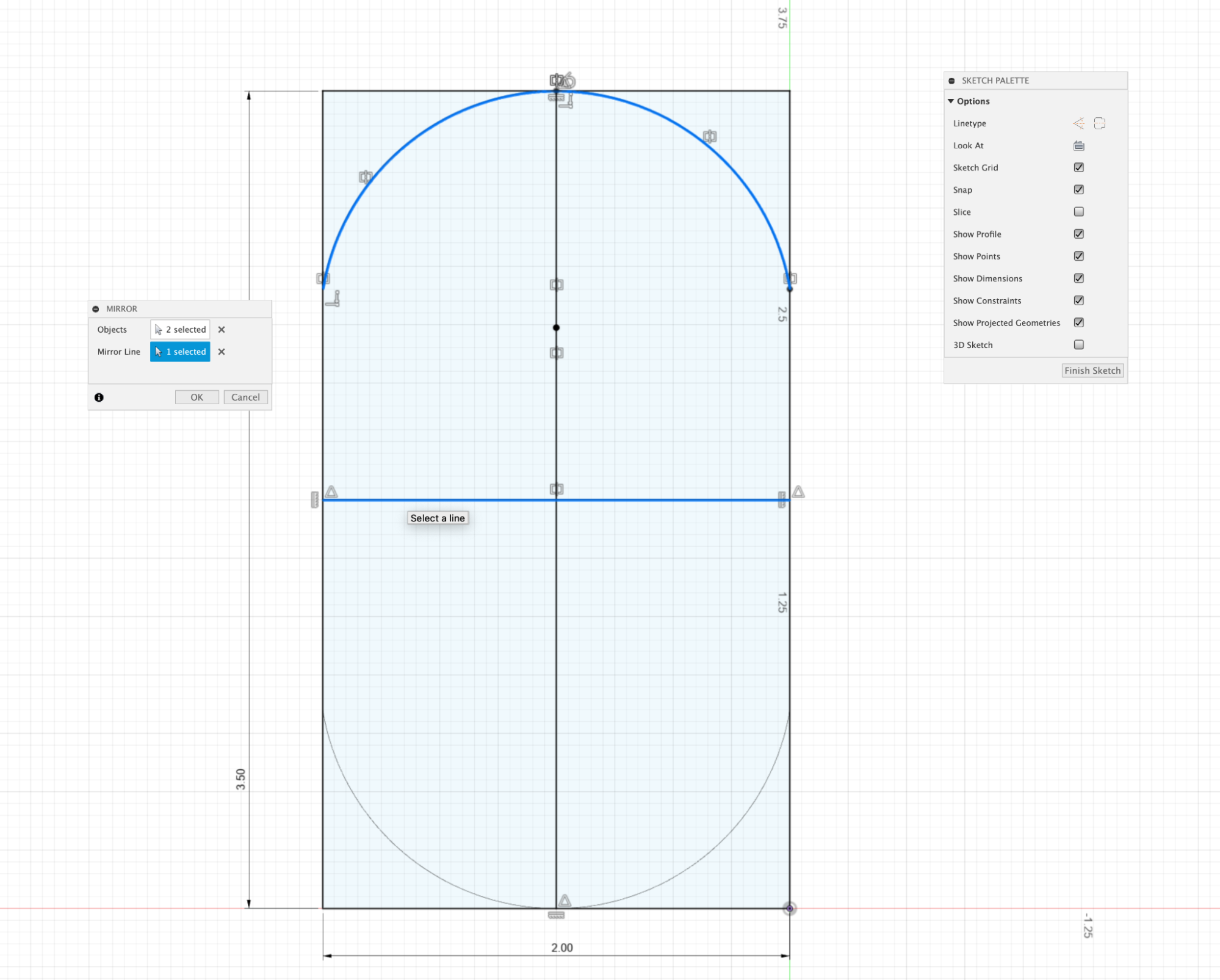
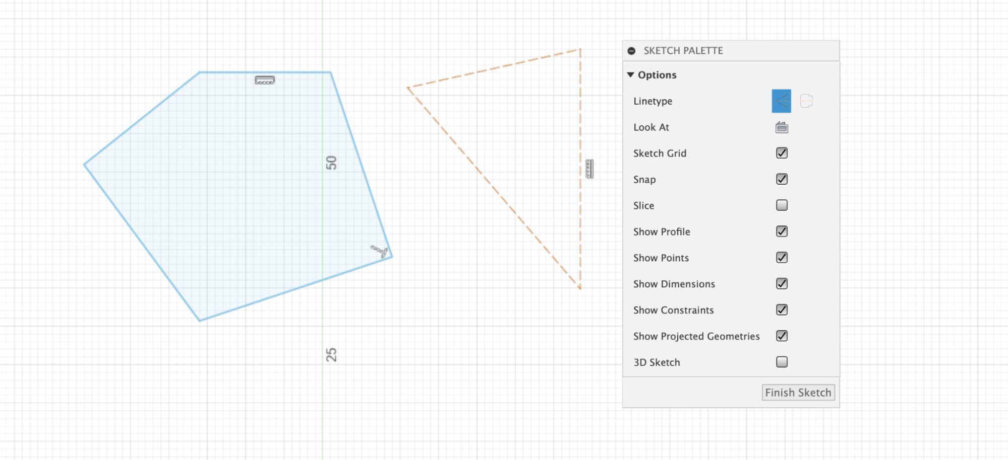
Side note- you can convert sketch geometry that you don’t want to convert into 3D geometry by using the construction mode linetype in the sketch palette:
Converting 2D Sketches into 3D Geometry
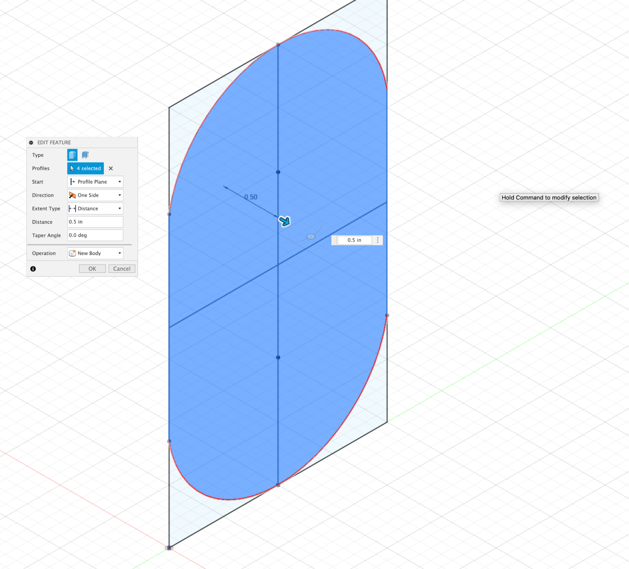
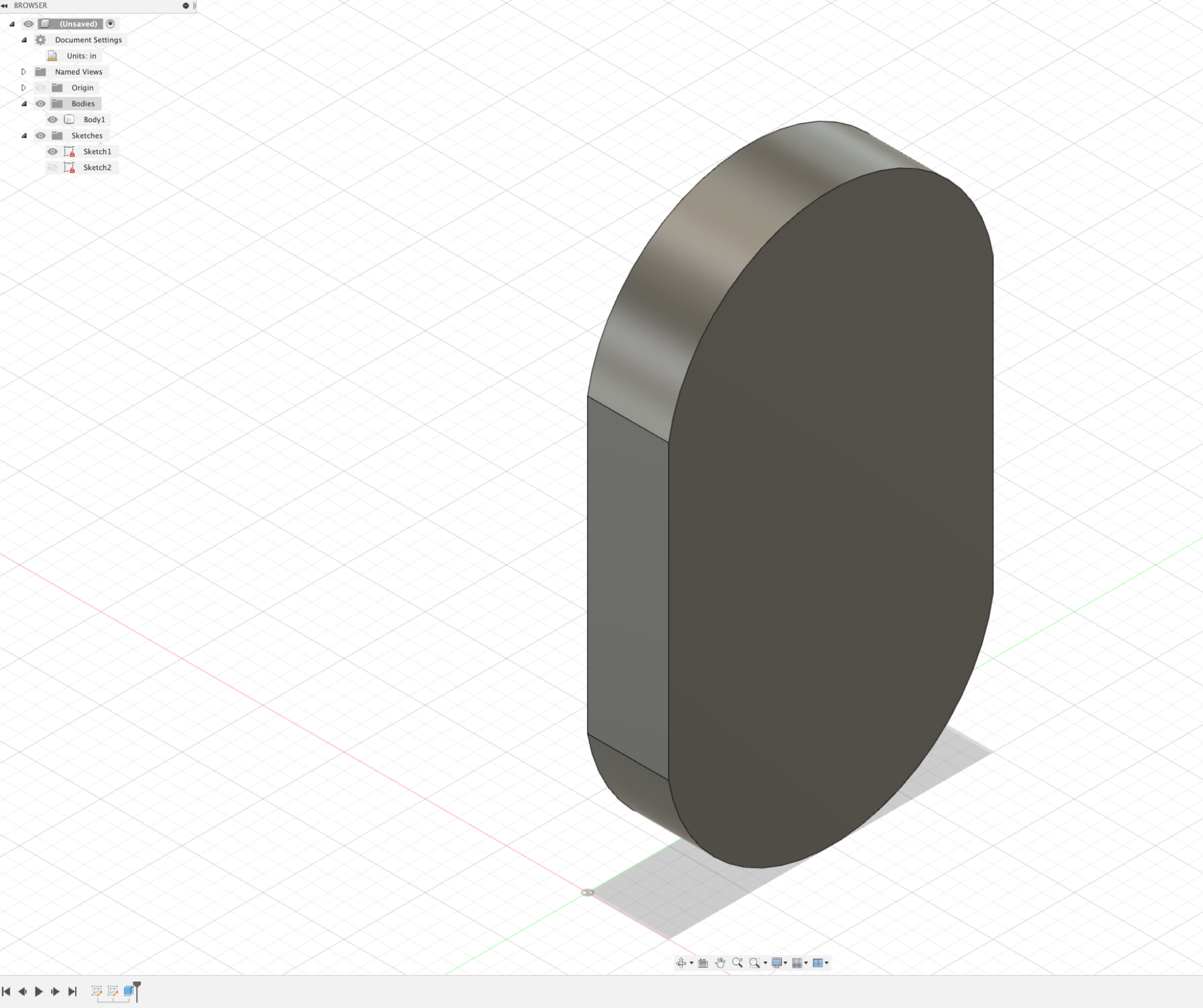
To create 3D geometry from our sketch, we can exit the sketch mode by selecting “Finish Sketch” from the sketch palette. Then we can extrude the 2D sketch to a 3D form by selecting the Extrude tool from the top horizontal toolbar.
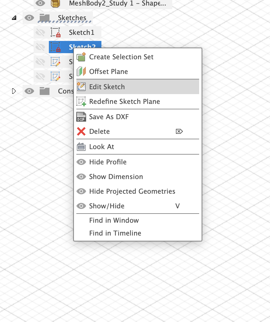
To create holes to mount our bracket, we can return to the original sketch by selecting it in the browser and editing it:
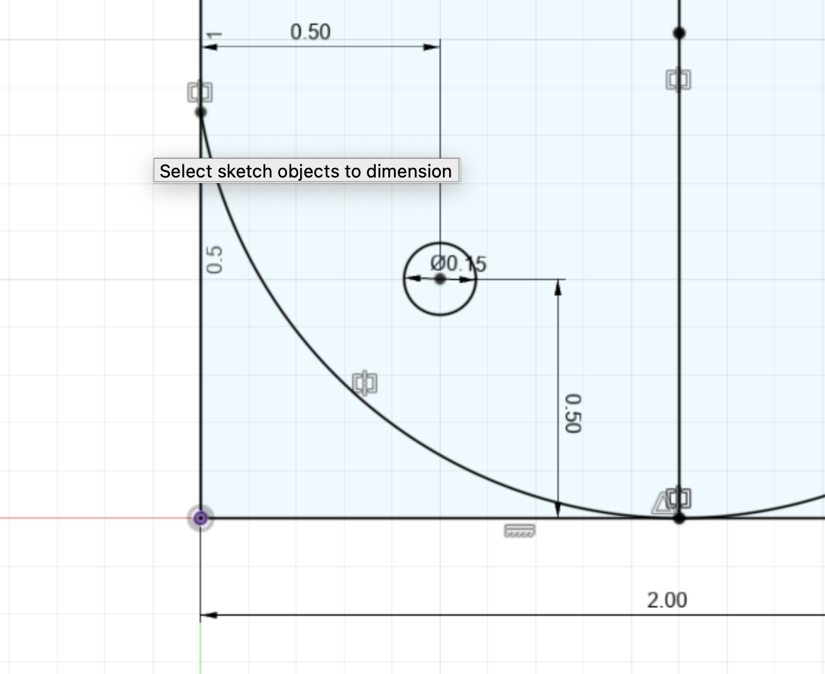
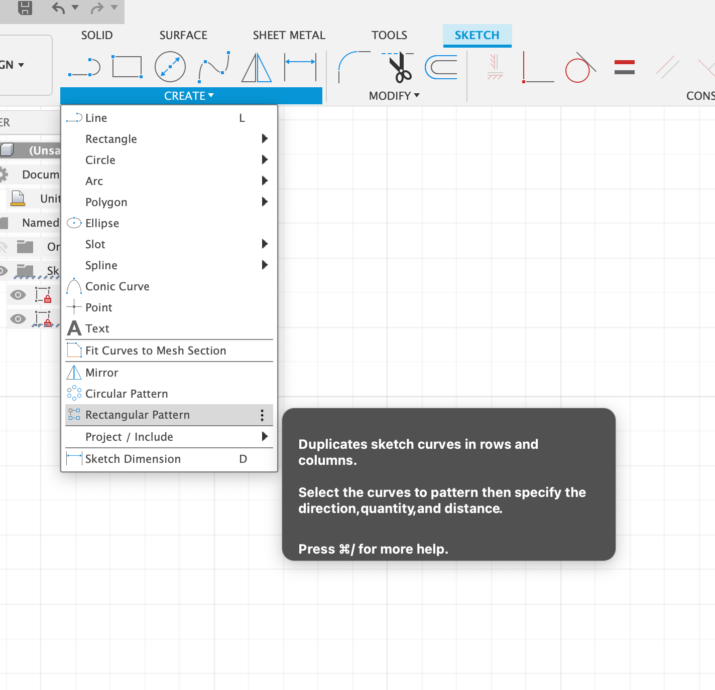
We can then use the sketch circle tool to create one hole offset from the corner of rounded rectangle. We can repeat this hole using the rectangular pattern sketch tool:
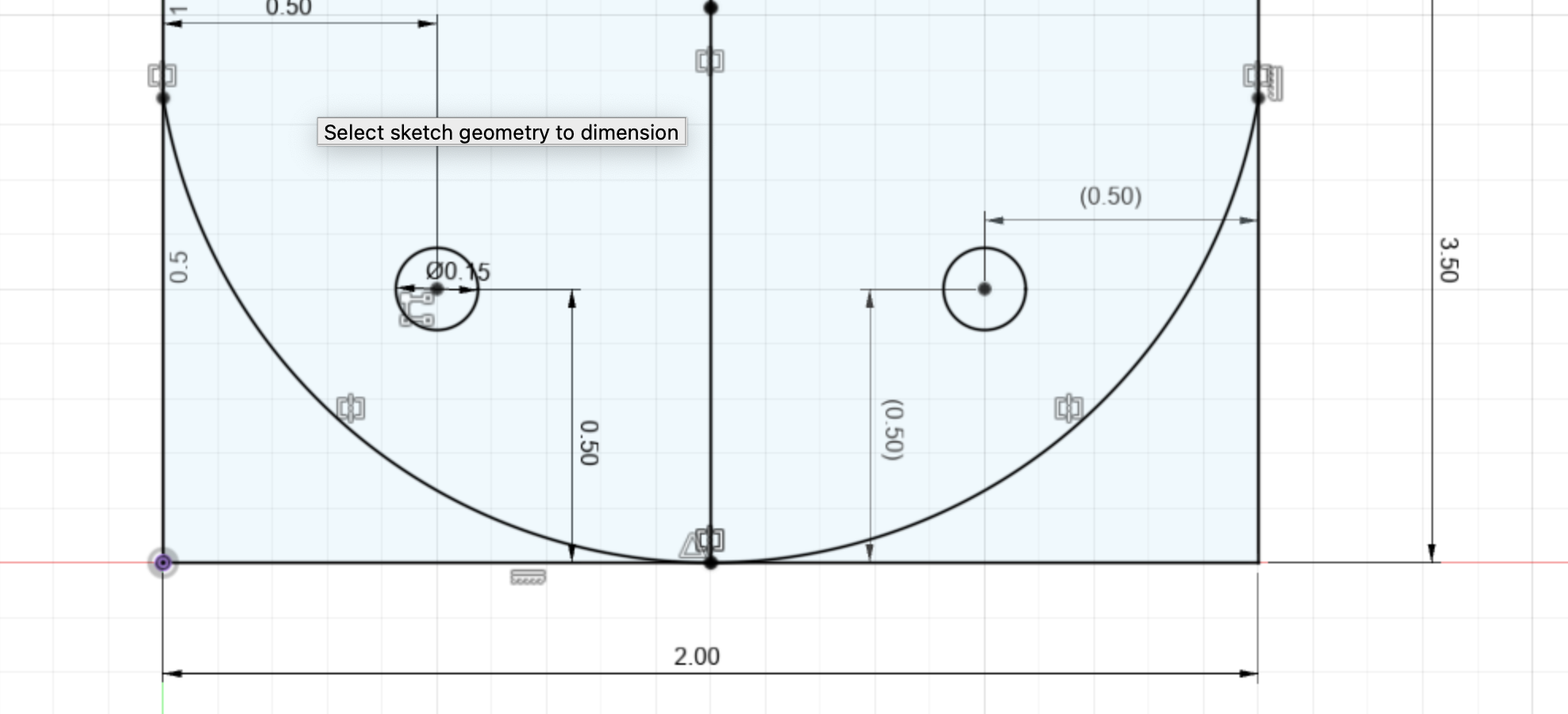
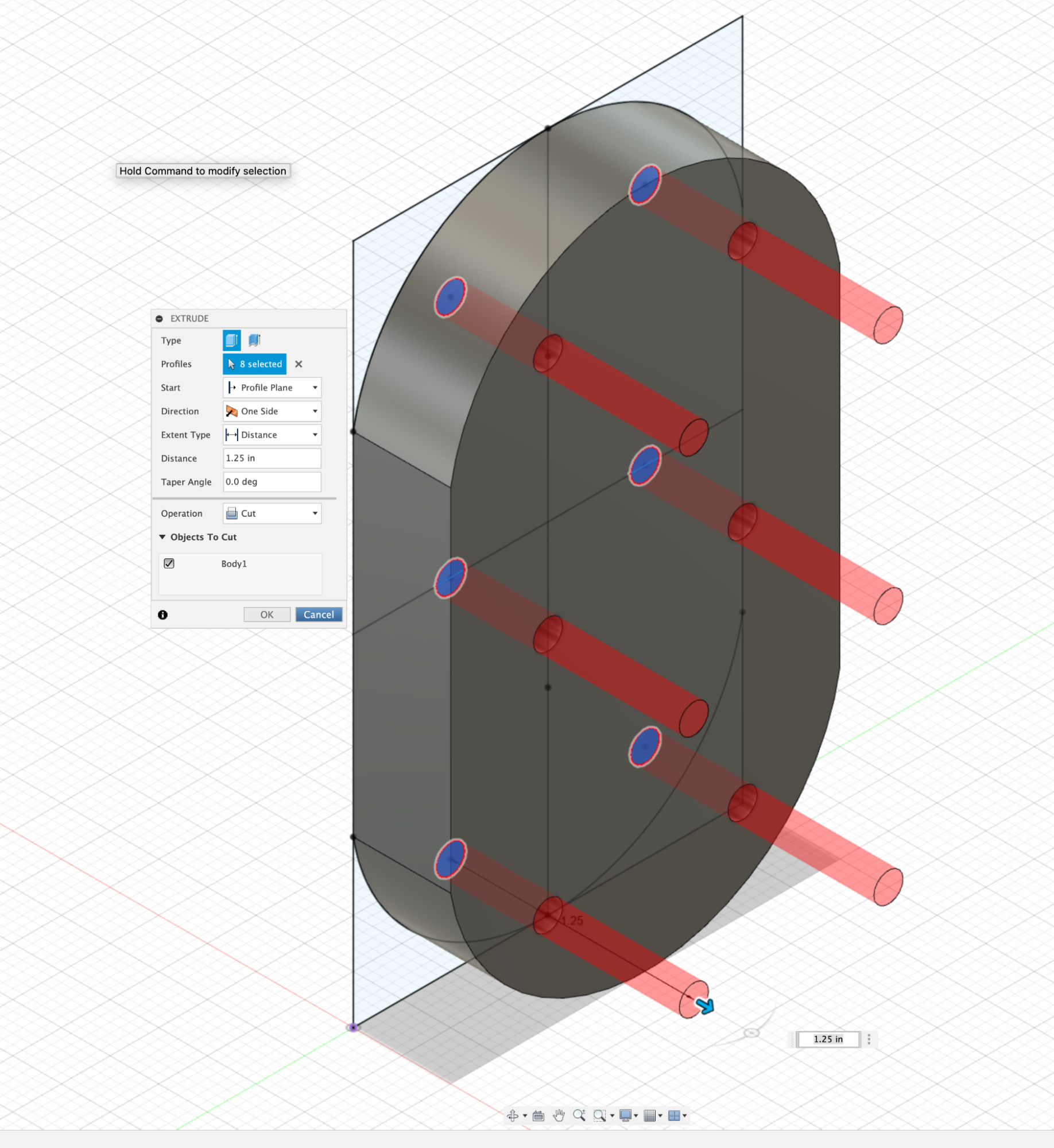
We can then perform an extrude action with these holes. By default the extrude tool will perform a cut operation, creating holes in our original mounting bracket.
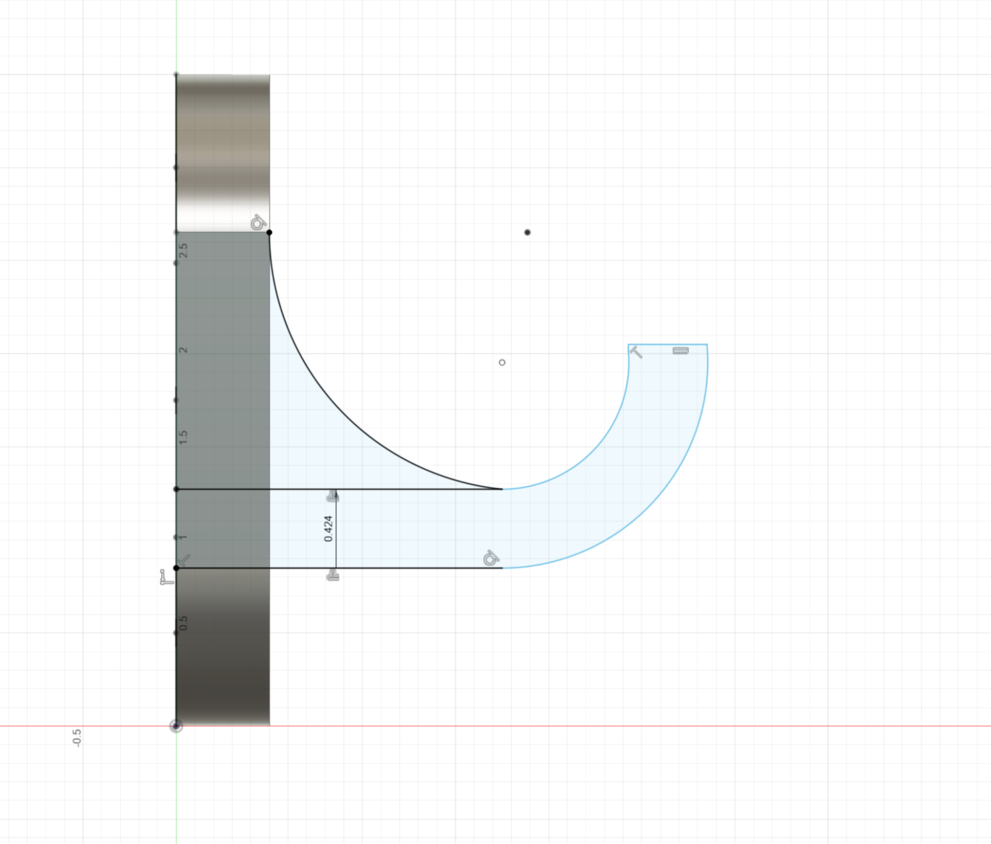
To create the hook part of our design, it’s useful to sketch from a different plane. We can create sketches relative to faces of existing 3D geometry. We’ll select the new sketch button and create a sketch on the face of the edge of our mounting plate bracket:
We want to extrude the hook sketch in a way that ensures that it is centered in our bracket. To do this, we can create a construction plane- an arbitrarily placed plane that we can position geometry relative to.
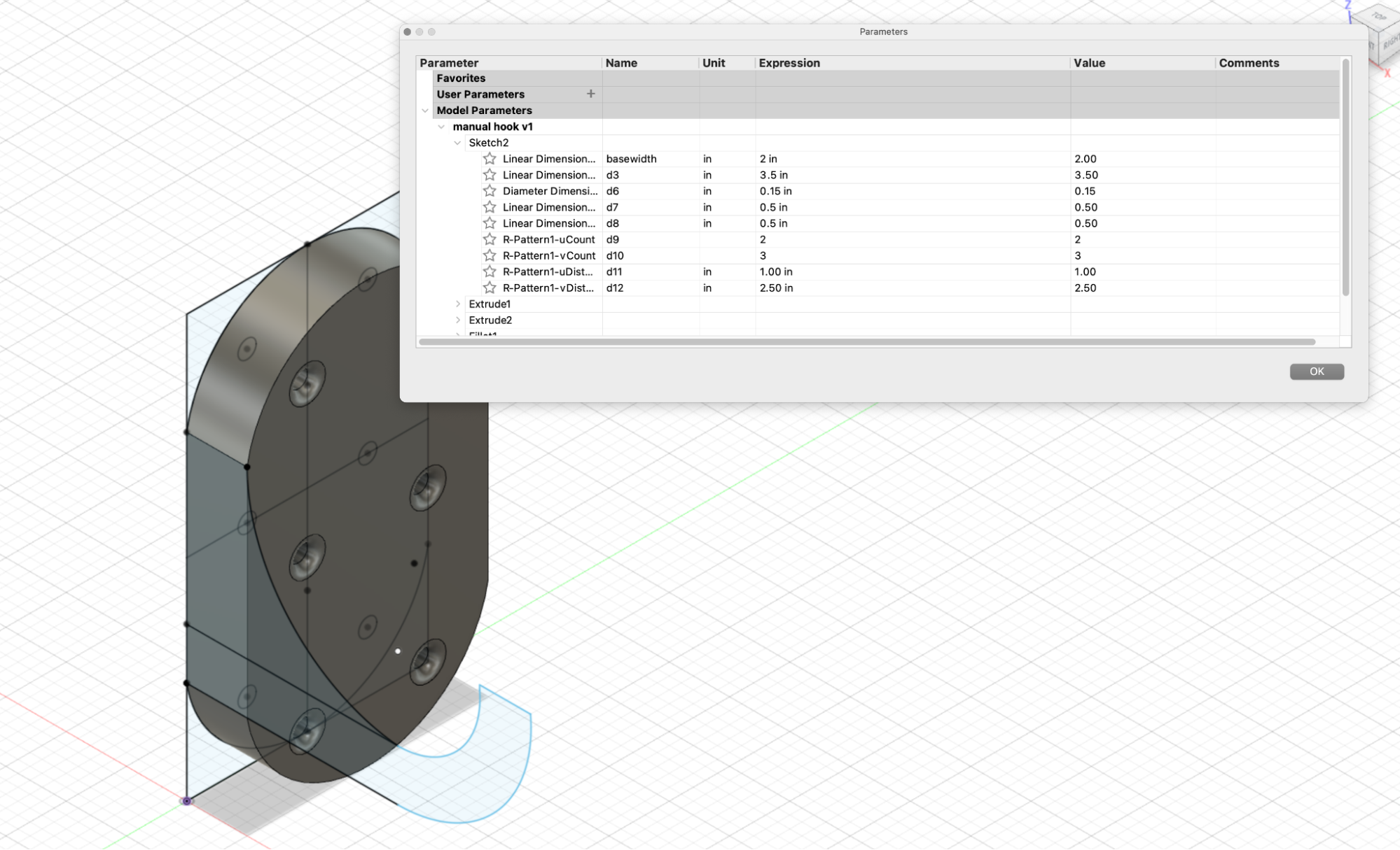
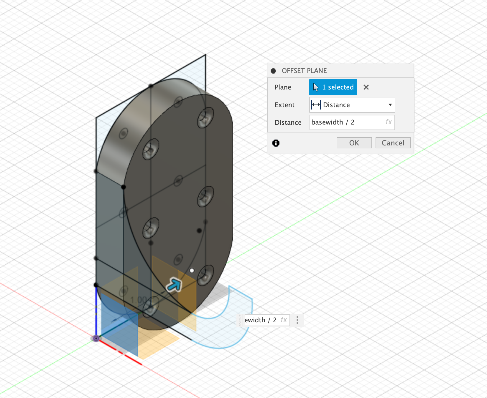
Using the construct menu, we can create a plane that’s offset from the x-z plane at a distance that will position it in the horizontal center of the bracket. To do this, we can reference the dimensions of our original bracket sketch. By selecting modify->change parameters from the top tool bar, you can pull up a table showing all the current dimensions of your project. We can rename the width dimension for our original rectangle sketch from “d2” to “basewidth”.
Then we can reference that value when creating the offset plane (basewidth/2):
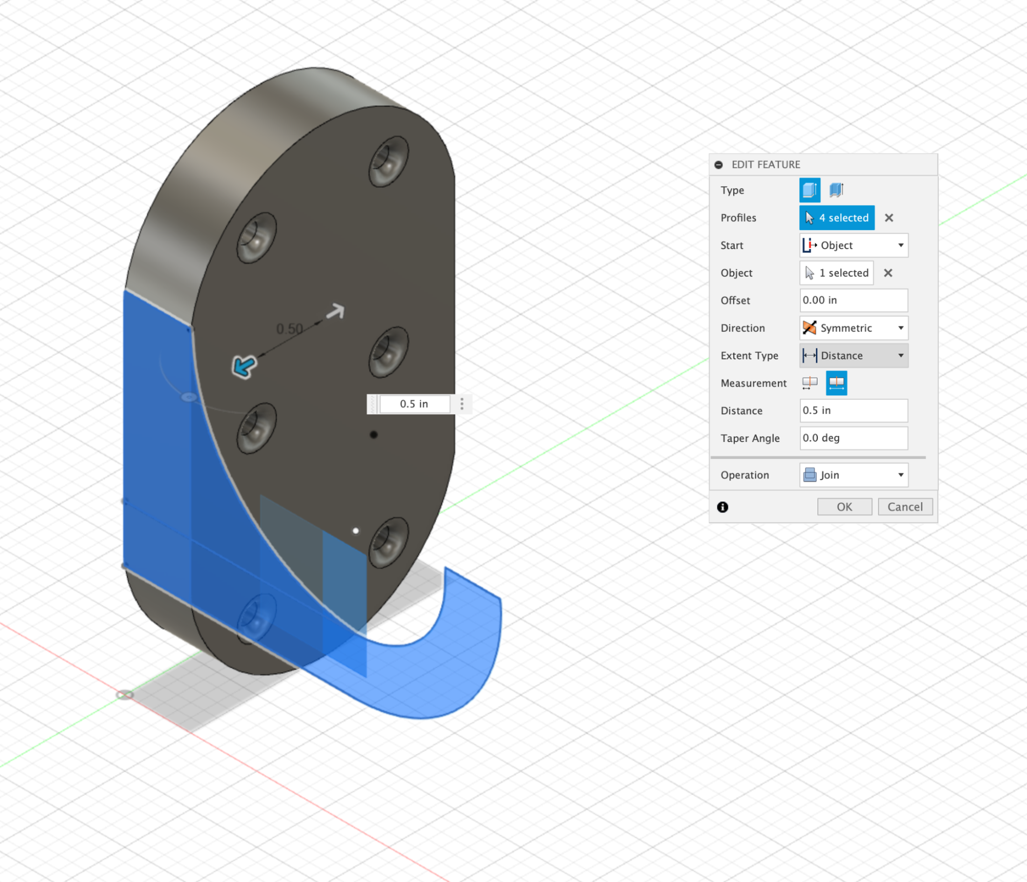
Finally we can extrude our hook symmetrically on both sides of the construction plane to create a hook that is centered in the mounting bracket.