How do coordinates work in Stepdance?
What is a coordinate system?
A coordinate system is a system that uses one or more numbers, or coordinates, to uniquely determine and standardize the position of the points or other geometric elements on a manifold such as Euclidean space.
Quote from the Wikipedia page on coordinate systems, which is a good refresher on what we mean by "coordinate system" and gives examples of common systems.
In simpler terms, a coordinate system helps us talk about the position of things in a given space, like a point on a page, your location on the Maps app, or the 3D position of your hand holding a VR controller.
Because we are working with an Axidraw plotter for now, we will be thinking in two-dimensions mainly (the paper on which we draw). In this case, we are interested in describing the position of the pen, in the 2D space of the paper.
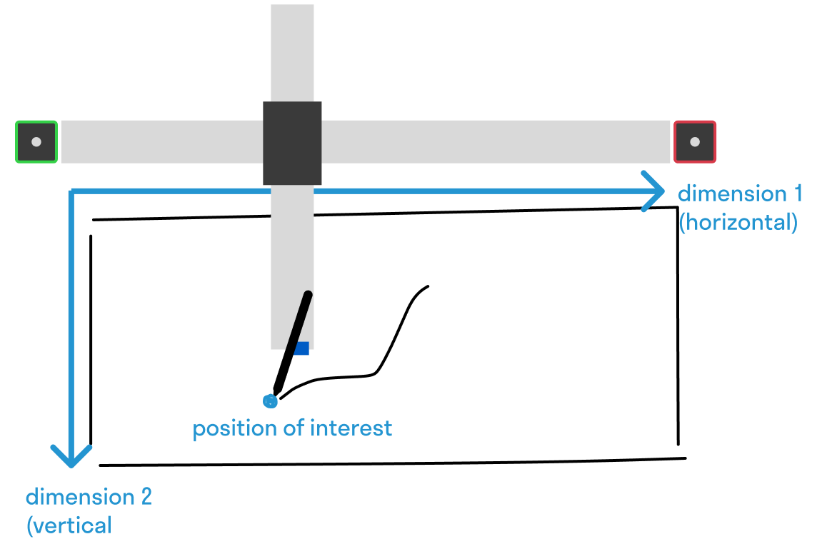
A straightforward way to describe that position is to define it by two measures (let's say in millimeters):
- how far along the horizontal axis are we? we call that measure
X - how far along the vertical axis are we? we call that measure
Y
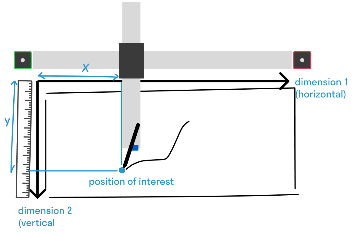
You may be familiar with this coordinate system from working on 2D graphics (eg P5, shaders, data visualization), where it is often referred to as the XY-plane, or screen-space, or the pixel grid. In digital graphics application, that coordinate frame is often defined for you: P5 enforces that the origin point is at the top-left corner of the HTML canvas element, that the X axis points towards the right and that the Y axis points down, with respect to your screen.
Stepdance coordinate system
The way Stepdance works is a bit different:
There is no inherent logic in Stepdance that enforces a given coordinate system by default! There is no pre-defined notion of an origin point, units, or axes direction. We can define one in our program ourselves.
And that is because we can use Stepdance to work with any sort of machines (potentially with more axes than 2, or with axes of an arbitrary length). The basic units and dimensions in the Stepdance library are in steps of the stepper motors along each axis, only the logic you program yourself (or by using functions from the library) will create a concept of a coordinate system for you to work in.
Let's take a closer look at how we define units, directions of axes, and origins for the Axidraw. We will be focusing on a 2D Cartesian coordinate system for this example, as it is the most straightforward way to cover the 2D plane (in particular, it is a lot like the familiar digital XY image space). Note that there are other coordinate systems that can be used, such as the polar coordinate system. We even provide Kinematics to work in polar coordinates, but that's not the topic of this guide, please refer to this example.
Axes directions and units
This is code we used in the last sketches:
void setup() {
    // ...

    // For the Axidraw V3: 2032 steps correspond to 1 inch (25.4mm)
    channel_a.set_ratio(25.4, 2032); // this defines the units
    channel_a.invert_output(); // this defines the direction in which the axes will point
}
The Channel ultimately sends steps as electronic signals to the motors (each step causes a small rotation of the motor axis), so we need to define for our particular stepper motors and actuation mechanism, the conversion between a linear motion of 1 inch (our distance unit) into a number of steps of the motor. This conversion we found by looking at the Axidraw V3 specification, and it will depend on the particular mechanism of the machine.
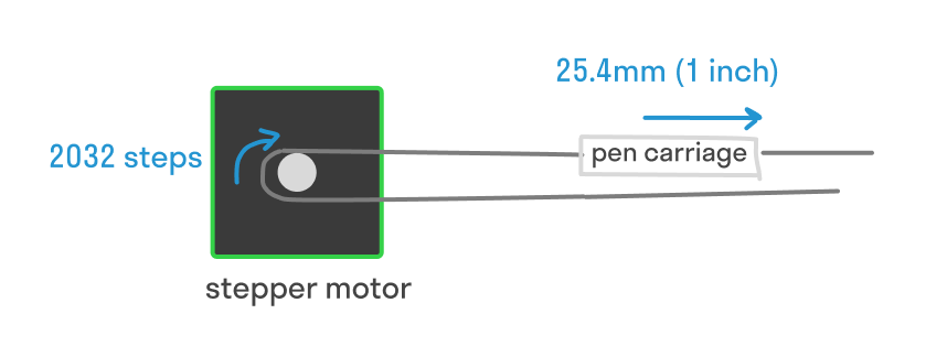
This code defines that we are reasoning in terms of millimeters as our unit. Hence, if you set as target value for channel_a.input_target_position or for axidraw_kinematics.input_x the value 10.0, we are thinking of 10.0mm. Feel free to use physical rulers from the lab to familiarize yourself with millimeters and measuring things out in the physical space from your plots.
We also define which direction the motor turns in to increment the axis. In this particular machine wiring/mechanism, we have to invert the default rotation direction (ie, turn motor "backward" to move this channel "forward").
Note that we also use the CoreXYKinematics to transform the coordinates of XY axes into motions of the A and B motors. See the Step-a-sketch guide for more details.
Origins (where is the zero?)
By convention, when the program first starts on the Teensy, all channels are set to zero. So, by that logic we can conclude that...
The origin of the coordinate system is wherever the machine is when the Teensy gets booted up (happens when uploading to it or when the Teensy gets unplugged/replugged).
Here are some example scenarios:
In this first scenario, I start up the Teensy with the pen roughly in the middle of the page. Note that I then need to use negative values to reach places to the left and up.
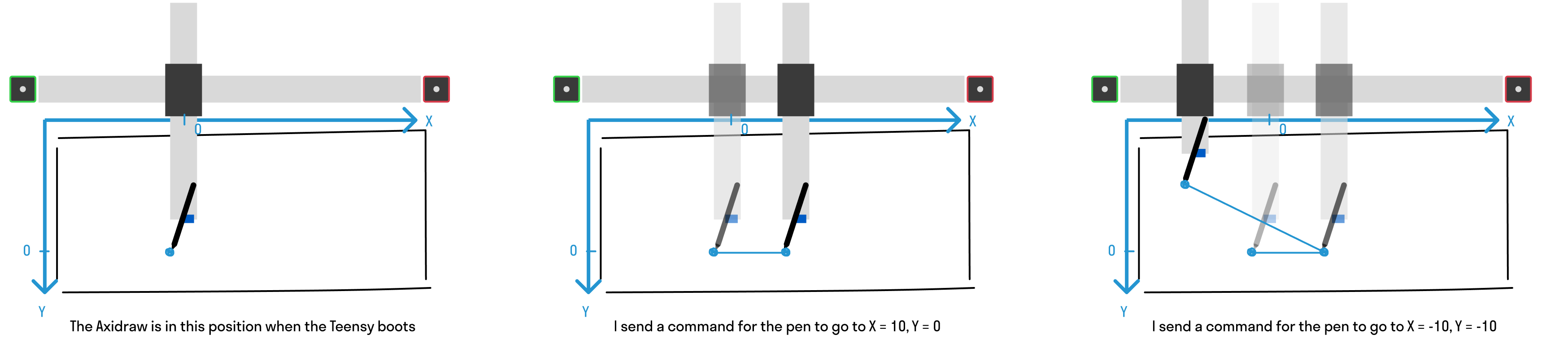
In this second scenario, I start up the Teensy with the pen in the upper-left corner:
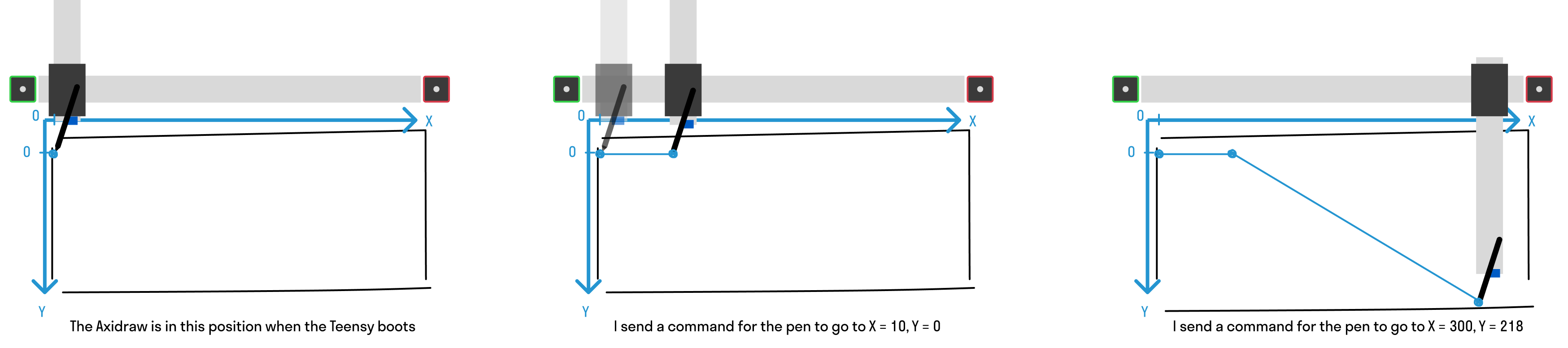
Note that this second configuration enables you to work with a coordinate system where the origin is in the upper-left corner. This is nice because now you know what is the maximum value that the axes can take before hitting the limits of the physical machine!
The dimensions of the Axidraw axes are roughly: width = 300mm and height = 218mm. This corresponds to an A4 paper in landscape mode.
Ok cool but does that mean I have to restart the Teensy every time I want to reset the origin?
Yes (and no). Restarting the Teensy (eg, unplugging and replugging the USB port) is a sure way to reset the origin to wherever the machine is upon replugging. In the next steps I will show a (slightly more advanced) way to reset the origin, as well as some tricks to avoid having to restart your Teensy.
Printing internal system state
There is no better way to understand coordinate systems than by playing with it!
Open the example sketch cmc_course/03_coordinate_system_playground in Arduino IDE, upload the sketch to the Teensy and open the serial monitor. We will use commands sent through serial to experiment with the coordinate system and better understand where things are in the coordinate system we defined.
For simplicity, you don't need to plug any physical input in for this example, all commands are sent through serial.
In this sketch, we continuously plot the Axidraw's X and Y values in the serial monitor, it should look like this:
13:45:09.915 -> Positions (X, Y):
13:45:09.915 -> 0.00,0.00
This informs us of the values that the system takes.
First experiment, let's use this serial command to disable the motors:
{"name": "motors_disable"}
With the motors disabled, move the axes of the plotter with your hands so that it is now in a different position. Re-engage the motors:
{"name": "motors_enable"}
What are the XY values in the serial monitor?
They are the exact same as before (0, 0), despite the fact that the machine-head was moved by you manually.
The Axidraw has no way of knowing in the absolute where its axes are, and any motion that happens while the motors are disengaged, or while the Teensy is unplugged, is basically transparent to the program.
This means that you can take advantage of the motors being disengaged to move the Axidraw into the position you want. For instance you can "home" it manually by bringing the pen to the top-left corner while the motors are disengaged.
In this sketch, we show also an example of re-setting the internal value of the axes. This can be called with the following serial command:
{"name": "reset_origin"}
This will reset the internal values of the position to (0, 0). In combination with manually moving the axes, this can help you re-home the machine. Check out the code of the sketch to see what method is called.
Sending a "go to point" command (Position Generator)
Now let's make the machine move to some pre-determined positions. Behind the scenes, this uses the PositionGenerator which we have played with last week. Please walk through the code to see the exact methods called!
We will use the serial command:
{"name": "go_to_x", "args": [10]}
Try to make the plotter go to its maximum horizontal and vertical extent. Take a ruler and measure -- does the measure match your numerical values?
Queuing multiple "go to point" commands (Time Based Interpolator)
The PositionGenerator does not allow us to queue multiple motion commands. Lastly, we show the TimeBasedInterpolator a new software component that is used under the hood by the Inkscape interpreter.
Here is the code that sets up the TimeBasedInterpolator:
// -- Time Based Interpolators for Pen XY --
TimeBasedInterpolator time_based_interpolator;


void setup() {
    //...

    // TBI (can be used to queue motions)
    time_based_interpolator.begin();
    time_based_interpolator.output_x.map(&axidraw_kinematics.input_x);
    time_based_interpolator.output_y.map(&axidraw_kinematics.input_y);
    time_based_interpolator.output_z.map(&channel_z.input_target_position);

    //...

    // Set up RPC etc...
    // {"name": "queue_xy_target", "args": [6, 5]}
    // args are: absolute X, absolute Y
    rpc.enroll("queue_xy_target", queue_xy_target);
}

void queue_xy_target(float x, float y) {
  time_based_interpolator.add_move(GLOBAL, 15.0, x, y, 0, 0, 0, 0); // mode, vel, x, y, 0, 0, 0, 0
}
And here is how to call it from the serial command:
{"name": "queue_xy_target", "args": [6, 5]}
What happens if you send multiple serial commands with different values?
The machine will go through each position sequentially. This feature can be used to plan a longer stream of motion! Each position gets stored in a queue upon calling the add_move method.